0
\$\begingroup\$

I want to run a 130V dc motor 2hp. I have 6 solar panel 120V dc out.

I connected them in series to the motor directly and it runs, but when I check the voltage at the terminal when it is running it read 60V. Where is the rest of the voltage and why not all the volt is use it up?

What can I do to make it run full power?

Second question: Can I attach a dc-dc boot converter at the end terminal of the solar panel and increase the voltage directly without using anything else? What is wrong with that idea?

thank you for your responses. I am trying to run a water pump. I have purchase a mppt unit that has 80v input max, and two lead batteries deep cycle, but I notice that I have to convert the voltage to ac then back to dc and make it 130v. how can I make this work, do I connect the panels in parallel and then charge batteries, have ac inverter and ac-dc inverter, I am not sure if this Is practical at all and how many batteries do I need, can I

\$\endgroup\$
6
  • 1
    \$\begingroup\$ Key questions: (1) What wattage rating are your panels, per panel. (2) 120V from 6 panels in series implies 20V per panel. Is that Vmp (V at max power) or Voc or ... ? (30 What are complete [panel specs? : Voc, Isc, Vmp, Imp, Wmp ... \$\endgroup\$
    – Russell McMahon
    Commented Aug 15, 2014 at 14:36
  • \$\begingroup\$ each panel is 18.5 vmp, 100 watts, 5.9 amp and 22.5 voc \$\endgroup\$
    – user51351
    Commented Aug 15, 2014 at 14:48
  • \$\begingroup\$ the mppt unit is Designed for 12V or 24V systems (max 250w for 24V, 125W for 12V) •Maximum charging current 9A •Maximum output current to load 7A \$\endgroup\$
    – user51351
    Commented Aug 15, 2014 at 14:49
  • \$\begingroup\$ At 18.5VMP, you'll need at least seven panels in series to get your 130VDC. At 5.9A max each, you'll need at least two seven-panel banks to yield the 11A (or more) that the motor requires. \$\endgroup\$ Commented Aug 15, 2014 at 14:59
  • \$\begingroup\$ IF you want full volts and batteryless operation then Panel Watts MUST be >= motor Watts. | Watts add with more panels. | Volts add with panels in series. Current adds with panels in parallel. | 18.5 Vmp panel x 6 = 11V = good enough (probably). | 6 x 100W = 600W = about 40% of rated motor power. 2 parallel strings of (6 series panels) is about OK. 3 strings better. \$\endgroup\$
    – Russell McMahon
    Commented Aug 16, 2014 at 1:29

5 Answers 5

1
\$\begingroup\$

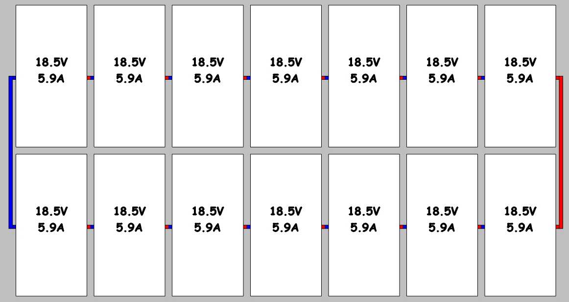
Wire your panels like so:

PV bank wiring

Wired exactly as shown, you'll get

18.5V * 7 = 129.5V
at 
5.9A * 2 = 11.8A
= 
129.5V * 11.8A = 1528.1W
\$\endgroup\$
5
  • \$\begingroup\$ i am sorry the drawing is hard for me to understand. if i connect 6 panel in series how do i connect them in parallel can you hand draw the wire connections or show me the wire connections please. this seems to be very helpful \$\endgroup\$
    – user51351
    Commented Aug 15, 2014 at 19:55
  • \$\begingroup\$ They're drawn in - the blue is the panels' negative leads, the red is the panels' positive leads. At the left of each panel is shown a short blue (negative) lead, and at the right of each panel is a short red (positive) lead. The wide blue line at the far left is the common negative, and the wide red line at the far right is the common positive. \$\endgroup\$ Commented Aug 15, 2014 at 19:59
  • \$\begingroup\$ ok i did this with only six panel.. i got 55.5 v only so the voltage dropped from 111 but the amp increase. what did i do wrong? but the voltage at the load side is 55.5.. the other way i had it the voltage was 55.5 but all panels were connected in series. \$\endgroup\$
    – user51351
    Commented Aug 15, 2014 at 22:38
  • \$\begingroup\$ I think you did it exactly right, if I understand you correctly, with two banks of panels in parallel and three panels in each bank, right? That's exactly the voltage I'd expect, if you did it that way. Now you just need a lot more panels in each bank to bring the voltage up. \$\endgroup\$ Commented Aug 16, 2014 at 0:54
  • \$\begingroup\$ i had to redraw my self to make sure i understood your drawing, i could not find this help anywhere on the web thank you again. \$\endgroup\$
    – user51351
    Commented Aug 16, 2014 at 4:59
0
\$\begingroup\$

The solar you are using have what is known as a load curve. This simply means that their output voltage and current follow a distinct relationship. You don't say, but the 120V is probably the open circuit (OC) voltage of the panel. Which means how much voltage it will generate with no load. At OC the panel will also not generate very much power.

To get the most out of your panels you need to have a MPPT controller (MPPT = Maximum Power point controller) which is essentially a fancy DC to DC convertor than allows the panel to operate at the point that allows it extra maximum power.

In short, you loading the panel too heavily. In fact it would be a very rare circumstance that you could operate the panels at their maximal point by directly connecting the motor as they have very different characteristics.

As long as you motor is not damaged by running at a low voltage and it can do what you need then this setup may be sufficient and you can get away without any fancy controllers.

\$\endgroup\$
2
  • \$\begingroup\$ with mppt I also going to need batteries and inverters correct,? I have to have ac inverter and ac - dc inverter? \$\endgroup\$
    – user51351
    Commented Aug 15, 2014 at 18:40
  • \$\begingroup\$ @user51351 it depends on what is available, but given this is a design site you'll have to find that info somewhere else to size it. Chances are that your panels don't provide enough power too, but we don't know since this information was not given. \$\endgroup\$ Commented Aug 15, 2014 at 18:50
0
\$\begingroup\$

The "where have all my volts gone" question is covered already.

"Can I attach a dc-dc boot converter at the end terminal of the solar panel and increase the voltage directly without using anything else? What is wrong with that idea?"

In order for a DC-DC converter to work, it has to draw even MORE current from the source (your panels) in order to pump up the voltage. Even in a perfect world, your net gain would be zero... but the DC-DC converter will ALSO waste some power (heat loss, etc), so your realistic net gain will be a net LOSS. Upshot: you'll have even LESS power to your motor than you have now.

If you're going to run that pump at the full rated 130VDC on photovoltaic, you're going to have to add more panels. Given that you're now reading 60V at the motor, you'll need AT LEAST twice as many panels to get the motor up anywhere near in full sun with perpendicular insolation.

The batteries... assuming 12V lead-acid batteries, you'll need them to store and deliver a total of at least 125 amps per hour to run that pump, probably more than that because the pump motor won't be 100% efficient. Count on twice that. If you're using photovoltaics to CHARGE those batteries, then the photovoltaics will need to supply enough to run the pump motor PLUS enough to charge the batteries. Your sum total power requirement will be more than twice as much as it takes just to run the pump, if the pump needs to run full-time. If the pump is only operated 50% of the time, you could load-switch... charging the batteries while the pump is off, not charging while the pump is running.

So... if the pump needs to run 100% of the time, AND you need to charge the batteries, then you'll need at least FOUR times as many PV panels as you now have.

\$\endgroup\$
3
  • \$\begingroup\$ dan lake mention that I am overloading the panels with just connecting them directly, what is wrong with that could it hurt the panels? how can I protect the panels, he also mention that I need more panels twice as much that is 12 panels in series, this would give over 260 volts but my motor is only 130 volt dc. can I burn the pump this way? \$\endgroup\$
    – user51351
    Commented Aug 15, 2014 at 18:47
  • \$\begingroup\$ It COULD damage the panels. It could burn out traces between individual cells, and once the first trace is burned, the rest of the panel could self-distruct quickly afterwards as the load gets taken up by fewer and fewer cells. Your solution will be to set up SIX or SEVEN in series with each other (we'll call each of these a "bank", then wire the BANKS in parallel with each other. I'll sketch it out & add it as an "answer" here. \$\endgroup\$ Commented Aug 15, 2014 at 19:11
  • \$\begingroup\$ thank you I looking forward to test it with help of your drawings \$\endgroup\$
    – user51351
    Commented Aug 15, 2014 at 19:22
0
\$\begingroup\$

I'm assuming that you meant the 6 solar panels give 120VDC when they're all connected in series. Not 120VDC each, and thus 720VDC in series. Please edit your question to clarify.

Anyway, the primary piece of information that you're not considering is the rated power output of the solar panels. Your motor is 2HP, which equates to about 1500 Watts. The power capacity of your solar array needs to be at least 1500W. A bit more, actually, to account for losses and less-than-peak sunlight. My guess is the panels you have add up to far less than that.

The reason you're seeing 60V is because the motor is overloading the solar panels. The panels are giving the motor literally every electron they're generating from solar energy. This has the consequence of driving the voltage down as the panels are starved of charge carriers. It's called a "brown out". The same thing happens when to the power grid sometimes. When the power plants can't produce enough energy to keep up with demand, the total voltage in the grid starts to drop, which makes everyone's lights dim.

The answer to your second question is yes. Since you gave no more information about what you're trying to do, I can give no more information than that.

\$\endgroup\$
7
  • 2
    \$\begingroup\$ Your last paragraph is wrong - a series configuration will give the same power to the "correct" load as a parallel to its "correct" load. \$\endgroup\$
    – Andy aka
    Commented Aug 15, 2014 at 8:23
  • 2
    \$\begingroup\$ Dan: No. Watts is watts. \$\endgroup\$
    – EM Fields
    Commented Aug 15, 2014 at 8:36
  • 2
    \$\begingroup\$ Dan: 10x 100W is 1000W any way you slice it, in series you get 120v at 8A, in parallel you get 12v at 80A. \$\endgroup\$
    – John U
    Commented Aug 15, 2014 at 8:47
  • \$\begingroup\$ @Dan Laks - we could edit your answer but it's better if you understand what people are saying and do it yourself. | Series - V's add, I's stay the same.| Parallel - I's add, V's stay the same. | Series or parallel - Watts add. \$\endgroup\$
    – Russell McMahon
    Commented Aug 15, 2014 at 14:34
  • \$\begingroup\$ In parallel, the voltages do not add but the CURRENT does. Power (V * A) remains the same as a series connection. \$\endgroup\$ Commented Aug 15, 2014 at 14:37
0
\$\begingroup\$

When the motor is running, the internal movement of the rotor creates a negative voltage according to the solar pannels polarity. So your diference of voltage is going exactly where it should; to power the motor.

\$\endgroup\$

Your Answer

By clicking “Post Your Answer”, you agree to our terms of service and acknowledge you have read our privacy policy.

Not the answer you're looking for? Browse other questions tagged or ask your own question.