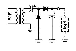
I'm a little lost as to what is going on in this circuit. The book I am reading mentions that the load would see double the voltage of the input voltage. How does this work?

I'm a little lost as to what is going on in this circuit. The book I am reading mentions that the load would see double the voltage of the input voltage. How does this work?
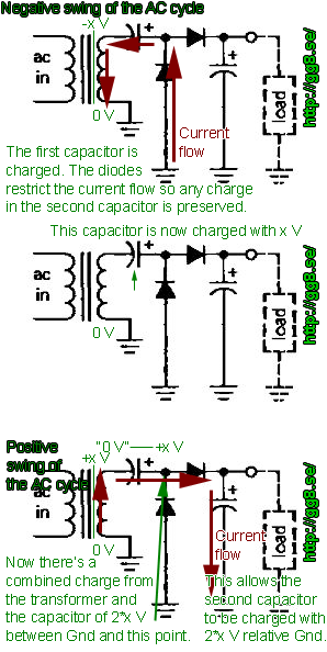
I've made a little GIF animation explaining what happens during the negative and positive voltage swing of the output.
The big thing to understand is that the first (left) capacitor is not fixed to ground on either side, but relative to the transformer output.
This allows it to first be charged at the negative part of the cycle, then be "lifted" above +x V at the positive swing.
The diodes restrict the flow of current such that none of the capacitors get discharged when the transformer swings to the opposite polarity voltage.

One way to think about voltage doublers like this one is to think about what happens with the voltages in a simpler, one-diode, one-capacitor type of circuit.
With one diode and one cap, the cap charges up to the peak voltage of the transformer secondary, but think about the voltage on the diode; when it is conducting, the voltage across the diode is just the forward drop, usually on the order of no more than a volt, but when it is non-conducting, it has to block the combined series voltages of the capacitor (charged to peak) and the transformer secondary, in the worst case also at peak. In other words, the voltage across the diode would be half-wave AC but with twice the peak voltage as the transformer secondary.
By adding a second diode and capacitor, using the voltage of the first diode as input, you can then get the peak voltage of the first diode to appear across the second cap, and there you are, twice the peak voltage of the transformer secondary.
Now, there are other ways to think about the circuit, equally valid, but hopefully this lets you make some intuitive sense of what's going on.
Perhaps it would be easier to understand how does this circuit works if you re-draw the scheme to be more obvious. Actually, this scheme with full explanation is given in:
http://www.cirvirlab.com/index.php/tutorials/92-diode-voltage-doubler-circuit.html
and there also possibility to see waveforms by simulating the circuit in:
http://www.cirvirlab.com/simulation/diode_voltage_doubler_circuit_online.php