35
\$\begingroup\$

I have been looking around for an easy way to convert 12V to 5V. I have seen some people saying that a simple resistor is all that is needed.

$$ Volts = Ohms \cdot Amps $$ $$ Amps = \frac{Volts}{Ohms} $$ $$Ohms = \frac{Volts}{Amps}$$

So applying a resistor will diminish the voltage of the circuit. That should mean that an appropriately sized resistor could simply be placed in the path of a 12V circuit, converting it to 5v.

  • If this is the case how would one reduce amps?
  • Would series vs parallel make a difference in this area?

I have seen designs that include a regulator IC and some capacitors, but if a simple resistor/fuse/diode setup will do the trick, I would really prefer that.

\$\endgroup\$
4
  • 2
    \$\begingroup\$ Are you trying to provide power to a load? What kind of load? Or are you trying to change the level of a signal carrying information? \$\endgroup\$
    – The Photon
    Commented Sep 2, 2014 at 16:51
  • 4
    \$\begingroup\$ Its almost never just about dropping voltage, its also about not wasting energy (efficiency), safety (resistors can get very hot) and regulation (maintaining the output voltage with changing load / current demand). \$\endgroup\$ Commented Sep 2, 2014 at 16:56
  • \$\begingroup\$ electronics.stackexchange.com/questions/83656/… \$\endgroup\$
    – jippie
    Commented Sep 2, 2014 at 19:30
  • \$\begingroup\$ Um, no there are much better ways to cut voltage. Use a 5V voltage regulator or if you're looking for something simple, just throw in a zener diode in reverse bias. \$\endgroup\$ Commented Sep 3, 2014 at 2:43

6 Answers 6

86
\$\begingroup\$

There are a few ways to get 5V from a 12V supply. Each has its advantages and disadvantages, so I've drawn up 5 basic circuits to show their pros and cons.

5 diagrams of different voltage regulators

  • Circuit 1 is a simple series resistor - just like the one "some people" told you about.

It works, BUT it only works at one value of load current and it wastes most of the power supplied. If the load value changes, the voltage will change, since there is no regulation. However, it will survive a short circuit at the output and protect the 12V source from shorting out.

  • Circuit 2 is a series Zener diode (or you could use a number of ordinary diodes in series to make up the voltage drop - say 12 x silicon diodes)

It works, BUT most of the power is dissipated by the Zener diode. Not very efficient! On the other hand it does give a degree of regulation if the load changes. However, if you short circuit the output, the magic blue smoke will break free from the Zener... Such a short circuit may also damage the 12V source once the Zener is destroyed.

  • Circuit 3 is a series transistor (or emitter follower) - a junction transistor is shown, but a similar version could be built using a MOSFET as a source follower.

It works, BUT most of the power has to be dissipated by the transistor and it isn't short circuit proof. Like circuit 2, you could end up damaging the 12V source. On the other hand, regulation will be improved (due to the current amplifying effect of the transistor). The Zener diode no longer has to take the full load current, so a much cheaper/smaller/lower power Zener or other voltage reference device can be used. This circuit is actually less efficient than circuits 1 and 2, because extra current is needed for the Zener and its associated resistor.

  • Circuit 4 is a three terminal regulator (IN-COM-OUT). This could represent a dedicated IC (such as a 7805) or a discrete circuit built from op amps / transistors etc.

It works, BUT the device (or circuit) has to dissipate more power than is supplied to the load. It is even more inefficient than circuits 1 and 2, because the extra electronics take additional current. On the other hand, it would survive a short circuit and so is an improvement on circuits 2 and 3. It also limits the maximum current that would be taken under short circuit conditions, protecting the 12v source.

  • Circuit 5 is a buck type regulator (DC/DC switching regulator).

It works, BUT the output can be a bit spikey due to the high frequency switching nature of the device. However, it's very efficient because it uses stored energy (in an inductor and a capacitor) to convert the voltage. It has reasonable voltage regulation and output current limiting. It will survive a short circuit and protect the battery.

These 5 circuits all work (i.e. they all produce 5V across a load) and they all have their pros and cons. Some work better than others in terms of protection, regulation and efficiency. Like most engineering problems, it's a trade off between simplicity, cost, efficiency, reliability etc.

Regarding 'constant current' - you cannot have a fixed (constant) voltage and a constant current with a variable load. You have to choose - constant voltage OR constant current. If you choose constant voltage, you can add some form of circuit to limit the maximum current to a safe maximum value - such as in circuits 4 and 5.

\$\endgroup\$
2
  • \$\begingroup\$ What about the "classic" voltage divider mentioned in @Scott Seidman's answer? How come it is not mentioned here? At first sight, it appears to be different from Circuit 1 here, since it contains an extra constant resistor in parallel to the [potentially changing] load. It would be nice to know what the consequences of choosing different R1 and R2 values are. What is their effect on the stability of the voltage when the load resistance changes? \$\endgroup\$ Commented Nov 13, 2019 at 0:11
  • \$\begingroup\$ Seems like 5th is the best, what about adding another capacitor after you get 5V to smooth out the spikes? \$\endgroup\$ Commented Aug 2, 2020 at 10:46
15
\$\begingroup\$

A resistor can only provided a fixed voltage drop if you send exactly the same current through it at all times. You would simply choose the resistor based on the amount of current so that it drops 7 V.

But most loads don't draw exactly the same current at all times, so this approach is rarely useful in practice. For a very low-current load (say, up to 50 mA), a linear regulator will produce a fixed output voltage with very little change in response to load current changes. For higher currents a buck-type switching regulator will do the same, but with much better power efficiency.

\$\endgroup\$
2
  • \$\begingroup\$ an inductor would fix the issue of constant current correct? could a capacitor be used to draw the needed current? and send the remainder back to the psu? \$\endgroup\$ Commented Sep 2, 2014 at 16:46
  • 1
    \$\begingroup\$ No. An inductor will slow down changes in current but not prevent them. \$\endgroup\$
    – The Photon
    Commented Sep 2, 2014 at 16:47
10
\$\begingroup\$

This depends very much on WHY you are trying to drop the voltage, and whether the LOAD is changing. To steal the picture from @Matthijs, enter image description here

Your circuit that you are trying to drop the voltage for as a whole goes between the points reflected by U2. If that circuit draws current, you need to account for that in the equations. Worse, if the current that circuit draw changes, so does the voltage U2!!

Sometimes, you can get away with dropping the voltage with a voltage divider, but other times you need to use some sort of voltage regulator.

\$\endgroup\$
1
  • \$\begingroup\$ Yes, but this equation does not give us a unique answer for R1 and R2 values. There is infinite number of R1/R2 pairs that satisfy this equation. How does one choose the proper combination from the infinitude of solutions? I presume that the proper choice should be based on the resistance of the load. But for some reason many answers tend to shy away from this extremely frequently asked question. \$\endgroup\$ Commented Nov 13, 2019 at 0:14
4
\$\begingroup\$

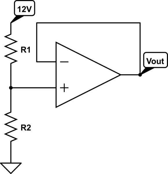
As others have mentioned you can use a voltage divider of two resistors, but the voltage divider output will change if the load current changes.

You can still use a voltage divider and fix this problem by adding a buffer to the output of the voltage divider. The easiest way (for you) to do this is to use an op amp configured as a buffer:

schematic

simulate this circuit – Schematic created using CircuitLab

The op amp has a very high input impedance so it won't load down your voltage divider.

You can also accomplish this with a source follower (MOSFET) or emitter follower (BJT) acting as your buffer if you don't want to use an op amp. However, you have to be more careful with biasing if you use a source or emitter follower.

\$\endgroup\$
1
  • 2
    \$\begingroup\$ While better than a divider, the op amp often still isn't the right way to to this, depending on how much current the load wants. \$\endgroup\$ Commented Sep 3, 2014 at 13:15
2
\$\begingroup\$

Lowering the voltage could be done using a voltage divider. It uses two resistors to "divide" the voltage as shown in the picture below.

enter image description here

\$\endgroup\$
2
  • \$\begingroup\$ I am assuming that u1 and u2 are v in and v out yes? \$\endgroup\$ Commented Sep 2, 2014 at 16:49
  • \$\begingroup\$ That is right. U1 is the voltage you want to "divide", and U2 is the voltage you want to use. Knowing these voltage you can calculate the resistors. Just pick a resistor for R1 and calculate R2. As noted in other answers, you need to dimension the resistor values in such a way that they can handle the current that is drawn by your circuit. This method is mostly used in very low current applications and where electrical noise is not a major issue to the circuit. (Example: I have made some guitar pedals that needed voltage different voltage levels, which I provided using a voltage divider) \$\endgroup\$
    – Matthijs
    Commented Sep 2, 2014 at 17:45
0
\$\begingroup\$

Voltage divider will do the job. If you are placing a resistor in the path of supply then it will only set the current not the voltage.

Based on your current requirement you can select the resistor and can configure it for voltage divider.

\$\endgroup\$
1
  • 1
    \$\begingroup\$ Voltage divider will only do the job for a fixed load. \$\endgroup\$ Commented Sep 2, 2014 at 18:35

Not the answer you're looking for? Browse other questions tagged or ask your own question.