1
\$\begingroup\$

I've got a Nema 17, rated at 0.8Amps, stepping angle of 1.8 degrees.

The motor looks like this, and has six wires coming out of it:
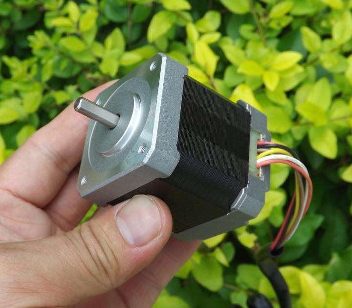
Nema 17

The four wires I've used are the ones labeled below (I was instructed to use everything except the black and the white one by my seller):
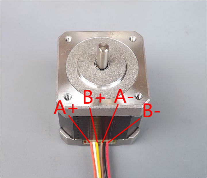
Wires

My current wiring:

Both the A+ and B+ wires are connected to A1 and B1 respectively. Likewise, A- and B- are connected to A2 and B2 respectively.
Wiring

I'm trying to use this motor with an Arduino Uno and a Polulu DRV 8825 driver. The power supplied to the motor is 12V, 500mA via the stepper driver.

I drive the stepper driver with two wires (one for the step, one for the direction). All my wiring is verified to be correct.

I'm trying to use this motor for my camera slider, but with no luck.

The problem

I want to achieve some really slow, yet smooth rotation with my stepper, but am unable to do so. Ideally, I'd like to reach speeds as low as shown in this youtube video.

When I try to vary the speed of the stepper speed through my code, it only marginally reduces in speed (definitely not as slow as I would like), and even when it does, there are a lot of vibrations at those particular speeds. However, there is only a (small) range of speeds wherein the motor is quiet. I'm afraid these vibrations may make my slider setup completely unusable.

Gearing isn't really an option either, due to the lack of space constraints (I want this slider to be lightweight and be able to fit inside a travel suitcase without much trouble.)

I've tried microstepping through my driver (DRV 8825), too - For the same speed values (as used with full steps), the motor coil can be heard to vibrate. And if I tweak the values to make the motor rotate, it seems to be some (approximate) multiple of the values I used for full steps previously, thus, again, making the motor usable only in the same ranges as it was in full step mode. Otherwise, the motor either vibrates fiercely or slightly, but without any rotation.

Solutions tried:

1) Microstepping (No luck)

2) Gearing (Tried and works, but can't use for my use case)

3) Different stepper libraries (Accel, PWM, etc.)

4) Variable resistor control (No luck)

At this point, I'm completely lost and clueless. Could it be something simple that I may be missing out? Or could it be something drastic, like having to change some main component (like the motor itself, or the driver)? Any help would be much appreciated and if any clarifications are required, I will be very happy to provide them.

Thanks!

My current code for Reference:

#include <AccelStepper.h>

AccelStepper stepper (1, 9, 8);
int MODE0 = 7;
int MODE1 = 6;
int MODE2 = 5;

void setup()
{  
   stepper.setMaxSpeed(15000);
   stepper.setSpeed(12000);
   pinMode(MODE0, OUTPUT); 
   pinMode(MODE1, OUTPUT); 
   pinMode(MODE2, OUTPUT);


   //Motor is now running in Microstepping mode (1/16)

   digitalWrite(MODE0, LOW);
   digitalWrite(MODE1, LOW);
   digitalWrite(MODE2, HIGH);

}

void loop()
{  

   stepper.runSpeed();
}
\$\endgroup\$
15
  • \$\begingroup\$ How did you decide how to connect the 6 wires of the stepper motot to the 4 outputs of the DRV8825? \$\endgroup\$
    – Andy aka
    Commented Sep 13, 2014 at 16:49
  • \$\begingroup\$ As per the docs which says I can do so, here: pololu.com/product/2133 \$\endgroup\$
    – dsignr
    Commented Sep 13, 2014 at 16:51
  • \$\begingroup\$ Hmmm you are not making this easy. I asked how did you decide how to connect the wires - I didn't want a link to a data sheet that ONLY gives HALF the story. Prove to me that you have wired it correctly. \$\endgroup\$
    – Andy aka
    Commented Sep 13, 2014 at 16:55
  • \$\begingroup\$ Sorry, that wasn't my intention. I'm using the unipolar stepper motor as a bipolar stepper motor. I connect the four wires to the four leads of the driver. The remaining two are left idle (as mentioned in the FAQ section of the docs I've linked above). Cheers! \$\endgroup\$
    – dsignr
    Commented Sep 13, 2014 at 17:10
  • \$\begingroup\$ Details of the 6 wires of which you used 4? \$\endgroup\$
    – Andy aka
    Commented Sep 13, 2014 at 17:23

3 Answers 3

3
\$\begingroup\$

Okay, turns out that there was an issue with a wiring too and the labeling was indeed incorrect on the motors. A big thanks to Andy for spending his precious time in assisting me.

How I solved the problem

Update: After discussion with one of the commenters below, it is learned that there is no difference in the order of wires connected to the driver, therefore, the order of wires labeled in my question and in the answer below don't matter as much as setting the value on the variable resistor itself.

These drivers have an onboard tiny variable resistor that limits the current to the motor. I just had to tweak it to get everything working. Now the motor runs in ultra low speeds, although with some mild vibrations (in full step mode).

After enabling the micro-step mode provided by the chip, I was able to dampen the vibrations by a huge margin and got everything working butter smooth.

For anyone else who may have this motor, here are some references:

Orange and Brown wires constitute one coil of this motor, with the black being the center tap.

Likewise, Yellow and Red constitute the second coil, with the white wire being the center tap.

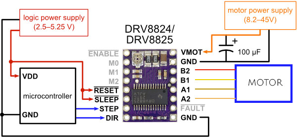
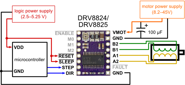
The way you connect it to a Polulu DRV8825 is as follows:

enter image description here

I hope this helps anyone else who may have the same issue.

Cheers.

\$\endgroup\$
6
  • 1
    \$\begingroup\$ This is problematic as an answer, as you say that the problem was with the wiring, but what you are doing now is no different than what your question implies you were doing before. It seems like you actual issue was that what you presented in the question did not match what you were actually doing. \$\endgroup\$ Commented Aug 14, 2016 at 16:11
  • \$\begingroup\$ If you pay closer attention to the diagram in the question, and the one presented in the answer, it does illustrate that the order of the wiring was different (and thus wrong) which is what the original accepted answer had suggested and therefore fixed in my answer as well. \$\endgroup\$
    – dsignr
    Commented Aug 15, 2016 at 2:56
  • \$\begingroup\$ There is no "order" of the wiring of a stepper motor. There are only coils, which you are identifying the same way now as you were from the start. If you change the polarity of connection to a coil, all that happens is the motor now rotates in the opposite direction for the same electrical sequence. \$\endgroup\$ Commented Aug 15, 2016 at 3:19
  • \$\begingroup\$ @ChrisStratton If the polarity of one pair of the coil isn't in accordance with the second pair, then the stepper motor wouldn't rotate (atleast in my case), but rather would just simply vibrate as it's trying to alternate between rotating left and right. Hope this answers why the order exists. Anyway, the order is an attribute of the answer that IS different from the question asked, thereby invalidating your points/assumptions about the question itself (that there is no difference in the system's connections from the question and answer). \$\endgroup\$
    – dsignr
    Commented Aug 15, 2016 at 3:26
  • 1
    \$\begingroup\$ You seem to be blaming something that actually does not matter. If you have a working stepper setup, and you disconnect the wires of one coil and swap them, the motor performance is not reduced at all. With a six wire motor you cannot reverse "half" of one coil relative to the other half - that only becomes possible with an 8 wire motor. About the only thing you could do with a six wire motor would be use all three wires, with the center tap on one terminal and both ends on the other, so that the field nullifies itself. \$\endgroup\$ Commented Aug 15, 2016 at 3:39
2
\$\begingroup\$

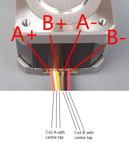
Just purely on how the wires enter the stepper motor from the picture supplied by the OP, there is a reasonable chance that A- and B+ are misnamed. Here's how I interpret the wiring to the two centre-tapped coils in the stepper motor: -

enter image description here

If this is the case, I'm unsurprised that the motor is not behaving correctly. I'm basing this on the fact that orange, white and yellow appear to be grouped as if they were to one of the coils and brown, black and red for the other coil. If this is so then the A- and B+ labels are erroneously switched.

\$\endgroup\$
6
  • \$\begingroup\$ This sounds likely. The OP needs to test with a multimeter. \$\endgroup\$ Commented Sep 13, 2014 at 17:56
  • \$\begingroup\$ Testing in progress, will update soon guys! Thanks a lot :D \$\endgroup\$
    – dsignr
    Commented Sep 13, 2014 at 17:59
  • \$\begingroup\$ Nope, Still no luck. Multimeter test shows the following results: [Orange-Brown = 8 Ohms] [Yellow-Red = 8 Ohms] [Orange-black, Brown-Black = 4.6 Ohms] And [Yellow-White, Red-White = 4.6 Ohms]. Therefore, white and black are the center taps. [Orange, Brown] and [Red, Yellow] are the required wires. But still, even after re-wiring, the behavior seems to be the same as I've described in the question - If I try to go below a particular speed, the motor just vibrates. There isn't much change in speed either, upon varying the speed in the code :( \$\endgroup\$
    – dsignr
    Commented Sep 13, 2014 at 19:20
  • \$\begingroup\$ Sounds disappointing - maybe the stepper motor sold to you is just not fit to do what you want or maybe it's a software thing? Did you confirm that there is no connection between yellow and black? \$\endgroup\$
    – Andy aka
    Commented Sep 13, 2014 at 20:56
  • \$\begingroup\$ Hi Andy, I just confirmed - NO connections between yellow and black and orange and white. I'm hoping that this is just a software issue, because, otherwise the motor has excellent torque (.55Nm). What else should I be looking at now that the wiring is confirmed to be fixed? Any pointers?? Thanks! \$\endgroup\$
    – dsignr
    Commented Sep 14, 2014 at 3:45
2
\$\begingroup\$

Your code can only set the micro-step mode if you connect the commanding outputs of your Arduino (pins 7, 6 and 5) to the corresponding inputs on the DRV882x shield (inputs M0, M1 and M2). Why else would the chip know what you want ?

\$\endgroup\$
1
  • \$\begingroup\$ Indeed - though apparently this was already done, but left out of the question. Since the poster's problem has apparently been solved, if the continued existence of the page on the site is going to have any future benefit, documenting the oversights like these is as important as anything else said here. \$\endgroup\$ Commented Aug 15, 2016 at 14:44

Your Answer

By clicking “Post Your Answer”, you agree to our terms of service and acknowledge you have read our privacy policy.

Not the answer you're looking for? Browse other questions tagged or ask your own question.