2
\$\begingroup\$

I am using a 3.3V uC (ATMega 328p in Arduino Pro Mini) running from 3 alkalines (nominal 4.5V). So Vin=4.5V, Vcc=3.3V

I'd like to drive LEDs from some pins, say at 20ma each. And I was thinking to connect the LED anodes to Vin (4.5v) with the cathode going to the uC pin, rather than putting all the LED currents through the 3.3v onboard regulator. (Also, while I'll use Red LEDs in the example here, I may want to use Blue as well, which would be more comfortable with a bit more driving voltage).

I figure a red LED at about 2v Vfwd, so the resistor would need to drop 2.5v @ 20ma, say 1K2 ohms.

The issue: this connect a uC pin to a source 1.2V about its Vcc rail (through an LED).

I think we are fine when the LED is on (pin low). But what about turning the LED off?
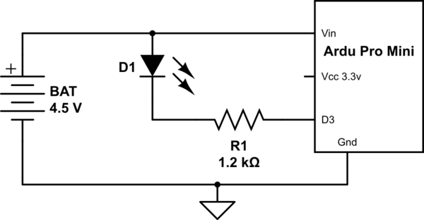
schematic

simulate this circuit – Schematic created using CircuitLab

Approach 1: Pull uC pin high (3.3v) to turn off the LED. The LED is between 4.5V and 3.3V, and the 1.2v difference will not be enough to light it - and I THINK it also won't bring the pin too high above its rail. But LEDs are not ideal devices, hence this question.

Approach 2: tristate uC pin (make it an input) to turn off the LED. The LED is between 4.5V and the high impedance input (along with it's static protection diode to Vcc). Again, I hope the LED's Vfwd would be enough protection for the uC pin.

Is either or both of these approaches workable and safe for the uC?

EDIT: substitute 120 ohm resistor above, oops.

\$\endgroup\$
7
  • 1
    \$\begingroup\$ I -think- that going high impedance or active low should be safe enough. But at these current levels why not just source current from the microcontroller's VCC rail as an output rather than a current sink/active low how it is now? \$\endgroup\$
    – KyranF
    Commented Sep 24, 2014 at 18:21
  • \$\begingroup\$ Remember that every pin/port of the ATMEGA has CMOS style clamping diodes to VCC and GND to deal with VERY low power over-voltage/negative voltage issues, but if you have a constant over-voltage condition with only a 1.2k resistor I think it will bust the CMOS diode clamps over time and break your entire port \$\endgroup\$
    – KyranF
    Commented Sep 24, 2014 at 18:25
  • 1
    \$\begingroup\$ @KyranF - If the pin is 'tristated', i.e. an input, then the LED should be below it's threshold, and be a very large resistance; it will be a "VERY low power over-voltage", so it won't be "constant over-voltage condition with only a 1.2k resistor". Having said that, I wouldn't do this unless I needed to fix something already broken, and this was my 'best option'. \$\endgroup\$
    – gbulmer
    Commented Sep 24, 2014 at 19:15
  • \$\begingroup\$ Agreed. unless the regulator is some ooddly weak thing, the only thing you are doing is shifting the power\heat loss from the regulator to the led resistors. While still having the 40/100/240 pin/port/total mA current limits. Sinking current to a low pin, has the same issues as sourcing current out of the pin. In this case, positive Voltage Droop. (er, lift?) \$\endgroup\$
    – Passerby
    Commented Sep 24, 2014 at 19:24
  • \$\begingroup\$ @Kyranf I used a red LED as an example, but a blue or green LED with Vfwd closer to 3V gets a bit tighter in terms of margins when powered from 3.3v out of the Arduino Pro Mini's (only about 0.3 V for the current limiting resistor). That's one reason I'd like to explore powering the LEDs directly from the 4.5v Vin. \$\endgroup\$
    – Zeph
    Commented Sep 24, 2014 at 21:12

4 Answers 4

3
\$\begingroup\$

What you're talking about is not huge risk for a hobby project.. a few things to think about.

It's not really the \$V_F\$ at the operating current that matters, it's the \$V_F\$ at the maximum 'off' brightness that is acceptable. That voltage might be as low as 1.4-1.5V volt for a low-current red LED- in a dark room they can be quite visible with microamperes of current. Driving the output to the 3.3V (nominal level) gets us 3.3V on the output. A fresh alkaline cell with minimal load might be 1.63V/cell at room temperature (just measured one), so 3 would be 4.89V. That leaves you with 1.59V across the LED + resistor (nominal, not allowing that the 3.3V might be a few percent low).

That's way too much to ensure it's not emitting a whole bunch of light.

So, we tri-state it- that allows the output to go maybe a bit above Vcc without much current flowing. 300mV is safe, the datasheet says 500mV absolute maximum. At 500mV, we'd have 1.09V across the LED, probably enough to ensure it's off, at least under nominal conditions. The 'absolute maximum' figure is never a good thing to design to, but usually there's a caveat on this particular figure that allows that voltage or a bit more if the current is limited.

So, I do think this will work (with tri-state, not push-pull), and I also think it's acceptable enough for a hobby project assuming nobody is going to be using a battery eliminator on the circuit in the future*. Keep in mind the margin on the red LEDs is minimal and consider eschewing red in favor of yellow or orange. Or, simply add a silicon diode in series with the red LEDs (one diode can be used for several LEDs).

  • If the ESD protection network in the ATMEGA328P does begin to conduct it will tend to raise up the 3.3V supply, out of control of the regulator. This is not a good thing for stability and could conceivably damage something, though the ATMEGA328P-M itself is rated for 5V operation.

I once did something like this in a commercial product (to drive a series string of LEDs with high Vf using a 5V constant-current output), but I designed a power supply with just the correct oddball voltage and appropriate temperature coefficient to match the LEDs and thus optimize the situation. I think the supply was around 8-9V. Worked a treat, easily from -20°C to 80°C (spec was 0-50°C).

\$\endgroup\$
2
  • \$\begingroup\$ Your reasoning is good and I would be convinced, but @Olin Lathrop comes to the opposite conclusion and alas, his reasoning sounds good to me too. Could you look over his answer and take his points into account? Thanks \$\endgroup\$
    – Zeph
    Commented Sep 25, 2014 at 18:06
  • \$\begingroup\$ I agree with Olin's reasoning, he's just got valid concerns about different things happening (that could affect, say, an analog input). If you want to be really safe, you can use a series diode as I suggested above with a bleeder resistor to ground for the red LEDs only, and drive the outputs push-pull as Olin suggests. Something like a 1N4148 with 10K to ground could supply many red LEDs. \$\endgroup\$ Commented Sep 25, 2014 at 18:52
3
\$\begingroup\$

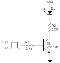
Subjecting a I/O pin to voltages above the processor's power level is not a good idea.

Use a transistor:

Added:

The correct solution that doesn't violate any parameters in the datasheet is above. However, if you are trying to get away with it, then it will most likely work if you make sure the output pin is always driven.

We are assuming a modern processor with a CMOS output. CMOS transistor can conduct current in both directions when on. The little bit of current you will get thru the LED when the output is high will be conducted thru the top driver transistor to Vdd. The value of that current at 1.2 V forward bias will be hard to predict, will vary significantly with temperature, and will vary part to part. However, it will be "very small" compared to the overall current draw of the processor.

If you switch the output between driven low and high impedance instead of driven low and high, then the protection circuitry for that pin will take the little LED current instead. For some designs, this is just a diode to Vdd and therefore no worse than having the top FET conduct. However, other designs have more complicated circuitry which would be worse to dump the current thru. Guessing what causes the least trouble is one of the problems you run into when ignoring specs.

There are two more ways to be fully in spec:

  1. Add a small bleeder resistor to ground. Size this to take whatever you determine will be the maximum LED current under all conditions. The LED may be very dimly lit when it's supposed to be off.

  2. Use a pin that has "5 V tolerant" input, and switch the pin between driven low and floating.

\$\endgroup\$
6
  • \$\begingroup\$ doing this would need an extra transistor and resistor than before, could be a bulky solution for driving lots of LEDs as seems to be their intent.. \$\endgroup\$
    – KyranF
    Commented Sep 24, 2014 at 19:01
  • \$\begingroup\$ As op has explained, the pins will never see a raw voltage higher than vcc. you Don't even attempt to answer the question. \$\endgroup\$
    – Passerby
    Commented Sep 24, 2014 at 19:26
  • 1
    \$\begingroup\$ Thanks for taking the time to draw up the conventional transistor approach. I am aware of that option, but as @KyranF understood, I'm checking whether I can trust Vfwd of the LED to protect the protection diodes, and feedback about which of the two approaches (pin = VCC or pin high impedance) would be better, in a context where adding the transistor and both resistors would be less convenient. \$\endgroup\$
    – Zeph
    Commented Sep 25, 2014 at 1:33
  • \$\begingroup\$ @Passe: No, the pin can see a voltage above Vdd. The LED will allow some current at 1.2 V forward bias. That could easily be, and probably is, enough to raise a high impedance pin above its supply voltage. \$\endgroup\$ Commented Sep 25, 2014 at 13:17
  • 1
    \$\begingroup\$ This answer is much improved, and has good reasoning for why active high for LED off would be safer than high impedance. Alas, another good answer from @Spehro Pefhany also has reasoning for why high impedance would be better. Could you take his/her reasoning into account and help me sort out which approach is better? Thanks \$\endgroup\$
    – Zeph
    Commented Sep 25, 2014 at 18:04
1
\$\begingroup\$

Your approach 2 (tristate the D3 pin) is okay except as other posters pointed out the ESD protection diode from D3 to VCC is in series with the LED (and resistor) when the output is tristated. There will be some small current flow there at (4.5V-3.3V)=1.2V across both diodes from the 4.5V supply to VCC. The LED threshold is much higher than the ESD diode's threshold of about 0.5V to 0.6V for appreciable current (microamps or more; they're big diodes), so at 1.2V across both the current is likely to be in the microamp range. However, the D3 pin voltage will go above VCC by about 0.5V to 0.6V and this probably exceeds the recommended voltage at the pad (for stress on the gate oxide of the input circuit transistors).

You're essentially using the D3 pin as an open drain NMOS switch. You could always add a discrete NMOS transistor off chip that can withstand > 4.5V. While it adds a component and inverts the sense of the port, it prevents overvoltage at the IC.

Note, none of the approaches so far provide current regulation, so the brightness will vary with resistor tolerance, temperature and supply variation. There are some simple schemes for that if you're interested, but they add a couple more components.

\$\endgroup\$
1
\$\begingroup\$

I figure a red LED at about 2v Vfwd, so the resistor would need to drop 2.5v @ 20ma, say 1K2 ohms.

You have to check your math on this one for your resistor value.

$$R = \frac{V}{I}$$

R = 2.5V dropped by the resistor / 20mA through the resistor = 125 ohms.

If you are not interested in adding a transistor, why not source the LED from the microcontroller pin?

\$\endgroup\$
1
  • \$\begingroup\$ Oops, did the divide quickly and wrongly in my head, you are correct. What advice would you give for sourcing a blue or green LED from a microcontroller pin with Vcc at 3.3v? I figure that the 0.3 V drop across the resistor is going to be highly variable, as the nominal Vfwd of the LED (around 3V) can vary by batch, temperature, etc. Vfwd varying by 0.1v makes a small difference when driving from 4.5v (1.5 vs 1.6 or 1.4 v drop across resister) but much more when driving from 3.3v. Or so I've heard. \$\endgroup\$
    – Zeph
    Commented Sep 25, 2014 at 17:54

Your Answer

By clicking “Post Your Answer”, you agree to our terms of service and acknowledge you have read our privacy policy.

Not the answer you're looking for? Browse other questions tagged or ask your own question.