3
\$\begingroup\$

For the design of a portable battery operated device, I have some power circuitry which requires a DC-DC converter and some other regulators, battery charger IC etc.

While in the process of selecting capacitors for the power system design, I noticed some leakage currents which were quite high, such as 220 micro Amps. If my battery is exposed to this kind of leakage current constantly, I'm sure there will be storage/long term usage issues.

What capacitor chemistry/types do you guys use for battery operated devices, but still for use in power filtering/supply roles? The battery charger IC has reverse blocking diodes/FETs built it, so I can assume that on the input side (external power input) it's okay for leaky capacitors. What do I do about the battery-side of the system? Rely on ceramic capacitors?

The sort of parameters I was looking for were 16-20V rated (for the input side) and 6.3V rated for the DC-DC converter output, and ripple current ratings up to 1A

\$\endgroup\$

2 Answers 2

6
\$\begingroup\$

Ceramics are usually the first choice for capacitors. One of their several advantages is very low leakage. The only reason not to use ceramics is if you need so much capacitance that they would take up too much space or cost too much.

At 16-20 V, you can get 10s of µF from ceramics. If that's enough, there is no reason to look further. If not enough, first try paralleling a few, then try specifically designing the circuit to require less capacitance. If none of those work, then you probably need to use electrolytics and live with the higher leakage current.

Note that leakage is probably specified at the worst condition, which will be highest voltage and highest temperature. Maybe the datasheet will tell you what leakage is at lower temperature, but you may have to contact a application engineer from the company to get definative specs. That's probably a good idea anyway, as they may be able to suggest other things you can do to minimize leakage.

Again though, the first reaction should be to solve the problem with ceramic capacitors.

\$\endgroup\$
5
  • \$\begingroup\$ I may design this first prototype with liberal use of bulk ceramic caps, with good thermal ratings (the X7R for Automotive/outside use) and if the input/output ripple in my system is unacceptable, I'll first debug by soldering on some electrolytics and if that fixes it, do a PCB revision to mount the electros where they worked/were needed. \$\endgroup\$
    – KyranF
    Commented Sep 29, 2014 at 16:38
  • \$\begingroup\$ May I ask if using ceramic bulk capacitance as an alternative for supplying the required capacitance for a DC-DC converter (buck) is going to work properly? Can ceramic caps actually handle "ripple" currents calculated to be around 1A while the converter operates? \$\endgroup\$
    – KyranF
    Commented Sep 29, 2014 at 16:55
  • \$\begingroup\$ @Kyran: Read the datasheet. Ceramics have much lower ESR, so can tolerate much higher ripple current than a electrolytic of the same capacitance. Again, this is all in the datasheet. \$\endgroup\$ Commented Sep 29, 2014 at 17:04
  • \$\begingroup\$ Indeed, I know ceramics have ultra low ESR. I suppose that does indeed mean they can take a belting without heating/failing. Thanks again \$\endgroup\$
    – KyranF
    Commented Sep 29, 2014 at 17:14
  • \$\begingroup\$ @Kyran: Yes, as the datasheet of any of them will tell you. Low ESR means low dissipation due to ripple current. \$\endgroup\$ Commented Sep 29, 2014 at 17:55
5
\$\begingroup\$

If you're using the typical 0.01CV+2uA type of formula to calculate the leakage current of an electrolytic, it's usually nothing like that after it sits for a while. More like a few uA to tens of uA which is often much less than the internal discharge current of a battery.

Here's a useful application note from Tadiran (who makes batteries designed for semi-permanent supply of power as for utility meters).

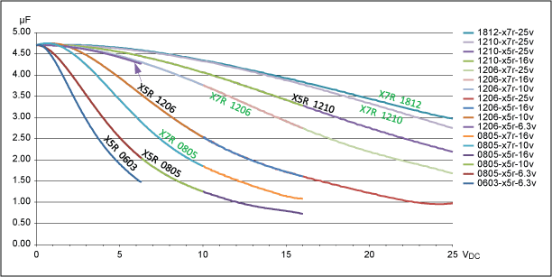
While perhaps in some applications it's worth the additional cost of ceramics, if you can get sufficient capacitance to meet specifications (taking the reduced capacitance with voltage and characteristic short-changing of initial capacitance into account) often it's not worth the cost. Voltage coefficient can be a huge factor in ceramics:

Edit:

http://www.maximintegrated.com/en/app-notes/index.mvp/id/5527

As you can see, a 4.7uF 16V capacitor X5R (reasonable tempco) practically disappears (drops to 1uF) when you put only 12V across it! They also age (as do electrolytics) but differently -- they drop in capacitance whereas electrolytic caps increase in ESR. The ceramic cap has an indefinite life (unless it shorts) whereas the electrolytic will eventually wear out as the ESR increases, but with proper design that can exceed the life of the product.

I would avoid the use of conductive polymer electrolytic capacitors in this kind of application. You can consider the use of a regular electrolytic cap in parallel with a ceramic (if required).

\$\endgroup\$
8
  • \$\begingroup\$ from your formula, i'm assuming the units for C are microfarads, and I get ~11.4 uA leakage. Check the "leackage current" characteristic for this panasonic capacitor: industrial.panasonic.com/www-cgi/… \$\endgroup\$
    – KyranF
    Commented Sep 29, 2014 at 16:26
  • \$\begingroup\$ you are saying that once they settle it's a lot less than what is usually listed? \$\endgroup\$
    – KyranF
    Commented Sep 29, 2014 at 16:28
  • \$\begingroup\$ Ah indeed. Your referenced app note shows why/how the manufacturer can quote such high values. Seems a lot less crazy that I thought. Thanks for the document! I found a document similar from AVX if you are interested: avx.com/docs/techinfo/LowDCL.pdf \$\endgroup\$
    – KyranF
    Commented Sep 29, 2014 at 16:32
  • \$\begingroup\$ @KyranF See my edit though, I don't think conductive polymer e-caps are as good for kind of thing. And avoid tantalum caps entirely if you can, too much of a tendency to go incendiary on you. \$\endgroup\$ Commented Sep 29, 2014 at 16:33
  • \$\begingroup\$ right, i'll try to find a standard electrolytic SMD cap then. \$\endgroup\$
    – KyranF
    Commented Sep 29, 2014 at 16:35

Your Answer

By clicking “Post Your Answer”, you agree to our terms of service and acknowledge you have read our privacy policy.

Not the answer you're looking for? Browse other questions tagged or ask your own question.