5
\$\begingroup\$

I am choosing parts to build an analog RC switch debounce circuit. I plan to implement the circuit described here: http://www.ganssle.com/debouncing-pt2.htm (see "An RC Debouncer").
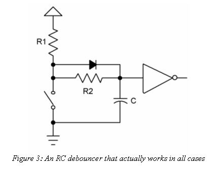
RC debouncer
(source: ganssle.com)

These are the other parts I plan to use for the circuit:

What part should I buy for the diode?

(Also, please point out any other mistakes I've made if you come across them -- my first time building a circuit. :3 I'm interested to see if it's a mistake to use a 1A AC/DC adapter or if my 2W resisters are correct for this circuit...)

\$\endgroup\$
1
  • \$\begingroup\$ Sorry about the lack of proper product links... Though I use stack overflow, this is my first time in the electrical engineering sub-site, so I can't post more than 2 links yet. :/ \$\endgroup\$ Commented Oct 27, 2014 at 1:30

3 Answers 3

4
\$\begingroup\$

Use a 1N4148 for the diode, assuming through-hole.

For the resistors, 1/4 W is more than adequate. The power dissipation is 25/82K = 0.3mW if you hold the switch down.

The adapter should be fine if it outputs 5V with no load (most will).

\$\endgroup\$
8
\$\begingroup\$

A simple RC circuit should suffice. You don't need that diode, just leave it away.

The most important part of that circuit is the Schmitt trigger, but it seems that you got that right.

As for the power rating, Spehr Prefhany is right, any standard 1/4W resistor will do.

\$\endgroup\$
2
  • \$\begingroup\$ "You don't need that diode, just leave it away" -- Ganssle thinks recommends it, check the link to his newsletter at the top of the question. \$\endgroup\$
    – tcrosley
    Commented Oct 27, 2014 at 3:34
  • 5
    \$\begingroup\$ I've actually read the link. He recommends it for when the "math goes haywire". OP uses the example from there, where tue math doesn't do that. I've built many debouncing circuits like this, it works just fine without it. The calculations are for the absolute worst case and very high component tolerances, to an extent that is a bit excessive. \$\endgroup\$
    – svens
    Commented Oct 27, 2014 at 8:56
4
\$\begingroup\$

I have used that self same circuit (from that very same source) for some time now. It works well, but I don't use the diode. I also don't use 2W resistors, but little SMD 0603 ones.

Also the component values I use are very very different.

For R1 I use 10KΩ. R2 is 100Ω, and C is 100nF.

I also don't use a specific Schmitt trigger gate since most MCU inputs are either Schmitt trigger anyway, or have enough noise rejection to not matter.

Unless you have incredibly noisy switches (I use tactile buttons with this circuit, which aren't that noisy anyway), you don't really need massive capacitance and large resistors to slow down the charge/discharge.

\$\endgroup\$
2
  • \$\begingroup\$ Hi I'm no expert by far but wouldn't the 100Ohm resistor with a 100nF Cap give you a 10uS RC charge time. Thought you should be aiming for the 20mS mark to account for the bounce effect. \$\endgroup\$
    – hoboBob
    Commented Dec 2, 2014 at 0:46
  • \$\begingroup\$ Hm, but isn't the debounce interval quite low with these values? For example, when assuming 5 V MCU with - say - 2.1/2.7 V input thresholds - I'll arrive at ~ 9 µs on button press (i.e. -1*100*10**-7*math.log(2.1/5)). And ~ 0.8 ms on release (i.e. -1*(100+10000)*10**-7*math.log(1-2.7/5)). Whereas conservative debounce intervals are specified with 20 ms. \$\endgroup\$ Commented Jan 22, 2022 at 13:24

Your Answer

By clicking “Post Your Answer”, you agree to our terms of service and acknowledge you have read our privacy policy.

Not the answer you're looking for? Browse other questions tagged or ask your own question.