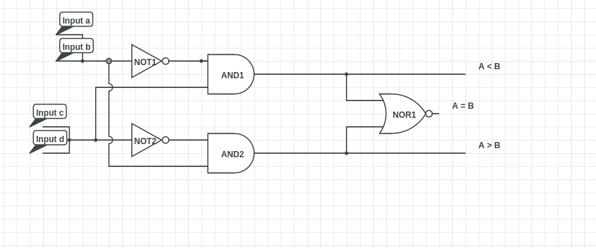
In digital design, you very rarely will connect multiple gates to a single wire or node (as you have done with a,b and c,d). This is because otherwise if one gate is trying to pass a '1' and the other a '0', there will be a fight between the gates which is usually a power->ground short (creating a lot of heat, an indeterminate logic level, and probably breaking some component).
The exceptions for this would be logic gates which will always produce the same output (same gate with same inputs, or something less common) or if the previous gates can enter what is called a 'high-impedance state' (tri-state inverter, transmission gate, pass-gate, or dynamic gates) to allow only a single gate to pass it's output to the node at a time.
Your description is very ambiguous. It sounds like you want to compare two numbers, X and Y.
X = 0,1,2
and
Y = 0,1,2
where
X = A + B (A/B = 0,1)
and
Y = C + D (C/D = 0,1)

If X > Y, O1 = 1, O2=O3=0.  If X = Y, O2 = 1, O1=O3=0.  If X < Y, O3 = 1, O1=O2=0
What is not clear to me is whether you want to treat AB and CD as digital numbers representing 4 distinct values(0,1,2,3), or as two separate bits representing 3 distinct values (0,1,2). I will assume as separate bits representing (0,1,2).
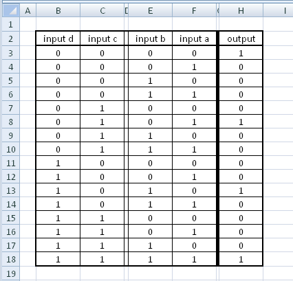
In this case, create a truth table:
A B C D    O1  O2   O3
0 0 0 0     0   1    0
0 0 0 1     0   0    1
0 0 1 0     0   0    1
0 0 1 1     0   0    1
0 1 0 0     1   0    0
0 1 0 1     0   1    0
0 1 1 0     0   1    0
0 1 1 1     0   0    1
1 0 0 0     1   0    0
1 0 0 1     0   1    0
1 0 1 0     0   1    0
1 0 1 1     0   0    1
1 1 0 0     1   0    0
1 1 0 1     1   0    0
1 1 1 0     1   0    0
1 1 1 1     0   1    0
Now take each output individually and create a Karnaugh map. If you have any terms show up in multiple outputs, you can save logic gates and re-use the logic! Or, use a online Karnaugh map calculator: karnaugh-auto
\$O1 = B\mathbf{\overline{C}\overline{D}} + A\mathbf{\overline{C}\overline{D}} + AB\overline{C} + AB\overline{D}\$
\$O2 = \overline{B}\mathbf{\overline{C}\overline{D}} + A\overline{B}\overline{C} + \overline{A}B\overline{C}D + \overline{A}BC\overline{D} + ABCD\$
\$O3 = \overline{A}\overline{B}D + \overline{A}\overline{B}C + \overline{A}CD + \overline{B}CD\$
Where variables which touch means 'AND'; '+' means 'OR'; the $$ \overline{Bar} $$ means inverse the variable. I bolded one like term that could be reused, I am sure you can find a lot more.
You don't have to find O2 that way, you can just do a NOR as you showed in your initial attempts on O1 and O3. Which if you worked out should be the same:
\$ O2 = \overline{(O1 + O3)} \$


