2
\$\begingroup\$

I studied circuit diagrams of some computer ATX power supplies. Some of them have got a Zener diode at the very end of 5V stand by line.
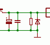
enter image description here

The picture shows endpoint of the circuit - the SMPS is on the left (outside of the picture), then there are two capacitors, a resistor and a Zener diode - all parallel to the circuit. The 5 Volt output is on the top right of the picture. I expect the capacitors filter the output, the resistor is necessary to provide some minimum load in order to let the SMPS regulation work correctly. But what is the purpose of that Zener diode? It is rated 6V2, i.e. 24% higher than nominal output voltage. Is it some kind of a protection in case of regulation malfunction? And will it really protect the load from overvoltage? And if so, why is so much higher valued than nominal 5 V?

Sources:

\$\endgroup\$
2
  • 1
    \$\begingroup\$ Post more of that schematic, please. Right now, the snippet is too small for us to provide a good answer. \$\endgroup\$ Commented Nov 5, 2014 at 1:04
  • \$\begingroup\$ OK, I added two links. \$\endgroup\$
    – Al Kepp
    Commented Nov 5, 2014 at 1:17

2 Answers 2

9
\$\begingroup\$

Zener diodes are provided at the output of SMPS for a couple of reasons:

1) Protection against regulation malfunction- say your voltage divider that serves as a voltage feedback is not soldered correctly. The output voltage (buck converter, say) can then rise all the way to the input voltage, which could destroy a number of components. Typical control these days is constant on-time or peak current control and such the output current is limited. Having the zener diode at the output will clamp the voltage to a reasonable level, the SMPM chip will limit the current.

2) To protect against unintentional back-feed that could destroy the SMPS regulator chip and propagate further.

3) The Zener voltage is higher because the knee characteristic starts just around 6.2 V and is not all that precise. 20% up will make sure the leakage current is minimal.

Source: power electronics engineer at General Electric.

\$\endgroup\$
1
  • \$\begingroup\$ I agree on 2), for example if this power supply is powering some 5V logic IC, which usually has diode from IO to VDD. Any overvoltage on IO pins will introduce injection current which will ultimately flow into this 5V power supply. Usually power supply can only source current but not sink current. If this injection current is larger than all the current consumption on 5V network, it will introduce higher voltage on 5V rail, which will destroy all the components. Add this Zener will shunt this injection current. \$\endgroup\$
    – iouzzr
    Commented Sep 21, 2020 at 8:24
0
\$\begingroup\$

My guess is that it is there to limit the output voltage. This would be because the 5Vstb specification are a bit different than those for the other outputs. From http://www.formfactors.org/developer/specs/ATX12V%20PSDG2.01.pdf:

3.3.6. Overshoot at Turn-on / Turn-off
The output voltage overshoot upon the application or removal of the input voltage, or the assertion/deassertion of PS_ON#, under the conditions specified in Section 3.1, shall be less than 10% above the nominal voltage. No voltage of opposite polarity shall be present on any output during turn-on or turn-off.

and

3.3.8. +5 VSB at AC Power-down
After AC power is removed, the +5 VSB standby voltage output should remain at its steady state value for the minimum hold-up time specified in Section 3.2.11 until the output begins to decrease in voltage. The decrease shall be monotonic in nature, dropping to 0.0 V. There shall be no other perturbations of this voltage at or following removal of AC power.

Maybe someone can confirm this?

\$\endgroup\$

Your Answer

By clicking “Post Your Answer”, you agree to our terms of service and acknowledge you have read our privacy policy.

Not the answer you're looking for? Browse other questions tagged or ask your own question.