5
\$\begingroup\$

I'm designing a PCB for USB 3.0, the specifications for Differential impedance comes at 90 ohms with a tolerance of +- 5 ohms.

I've used different calculation tools but when I have to hold these specs my traces are really wide in comparison to the usb3.0 printed circuits that I have as example, even with the same PCB material.

I searched the Internet and found some specs for the width and spacing but if I put those into the calculation tool it shows 170 ohms..

Anyone have an idea how manufacturers solve this?

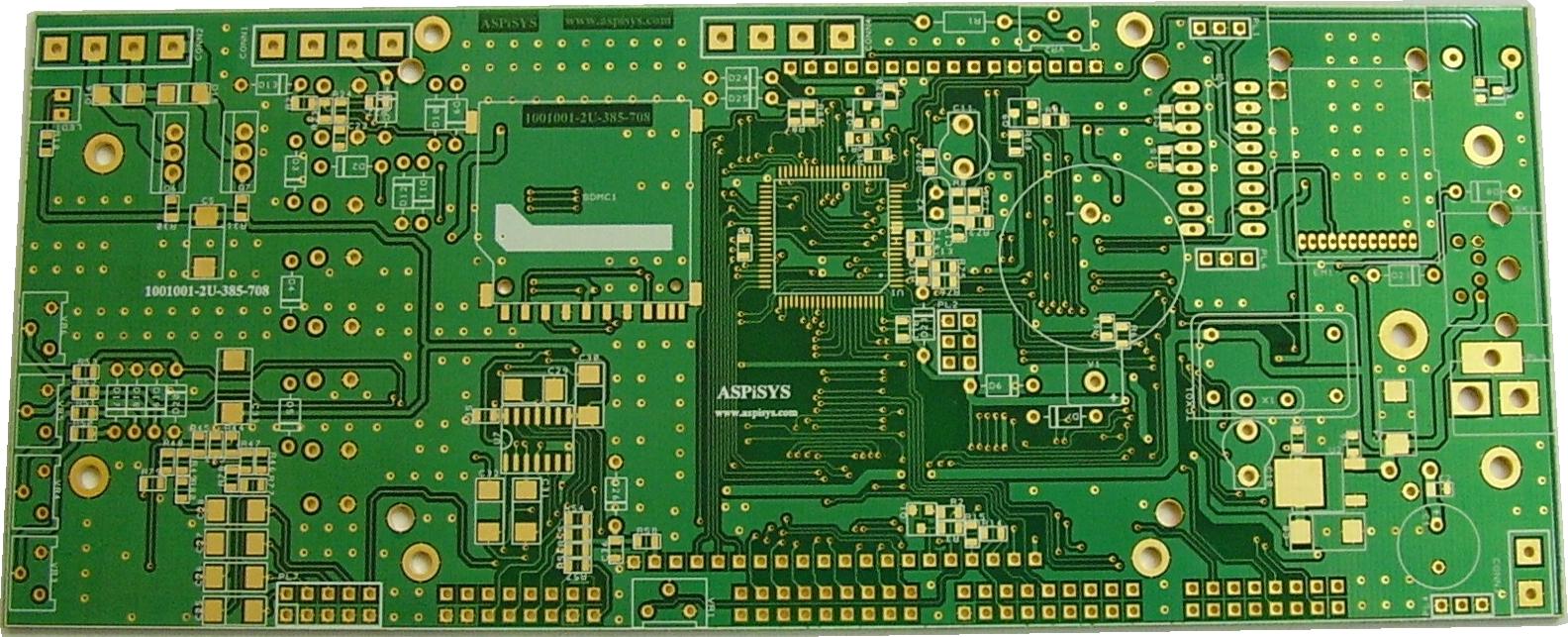
I also had a question about manufacturers putting multiple Vias from top layer to bottom layer. In the past I read some articles about this but can't seem to remember what it's for, anyone have an idea about that?

Here is an example : http://www.aspisys.com/netqe128.jpg
\$\endgroup\$
4
  • \$\begingroup\$ How far above your reference plane are your traces? The vias are stitching vias probably for emi, there are different schools of thought on those :) \$\endgroup\$ Commented Nov 7, 2014 at 13:40
  • \$\begingroup\$ I was thinking of working with a 2 layer PCB of 1.6mm thickness the usb 3.0 data traces on the top layer and a GND plane on the botom layer \$\endgroup\$ Commented Nov 7, 2014 at 13:49
  • 2
    \$\begingroup\$ That's why your widths are coming out high the pcbs you are using as reference are probably 4 layer with the reference plane more like 0.127mm below the traces. Try something like that in your calculators. \$\endgroup\$ Commented Nov 7, 2014 at 14:03
  • \$\begingroup\$ Please post two different questions as two different questions. \$\endgroup\$
    – The Photon
    Commented Nov 7, 2014 at 17:00

1 Answer 1

1
\$\begingroup\$

This is really two questions in one.

1) Impedance/trace width

If I remember my USB 3.0 (5-10GBps) spec correctly, it calls for:

  • cable = 85-95Ωdiff / 42-48Ωse
  • receiver = 72-120Ωdiff

What that means is that you should get by with 45-50Ωse target PCB trace impedance.

Remember you have +/-20% impedance accuracy on outer layers and +/-10% on inner layers unless you do something special for your production.

If the traces seem too wide, it just means you have the reference plane too far from the traces. Try some thinner materials in the range of 100-150um.

Remember to use a real 2D field-solver, not some odd formulas when calculating trace impedance for this. With the small geometries, odds are the formulas are out of their valid range.

2) Vias

As for the vias - a good guess is these are Gnd or Vcc vias. Good for interconnecting multiple planes. Recommended. I have however never seen digital boards requiring these vias to be "sprinkled" closer than about a one inch grid. And normally they are present already for pwr/gnd vias to connect to bypass caps.

I am assuming bypass is well engineered here.

Let me know if this helped? Feel free to ask more questions.

\$\endgroup\$

Your Answer

By clicking “Post Your Answer”, you agree to our terms of service and acknowledge you have read our privacy policy.

Not the answer you're looking for? Browse other questions tagged or ask your own question.