3
\$\begingroup\$

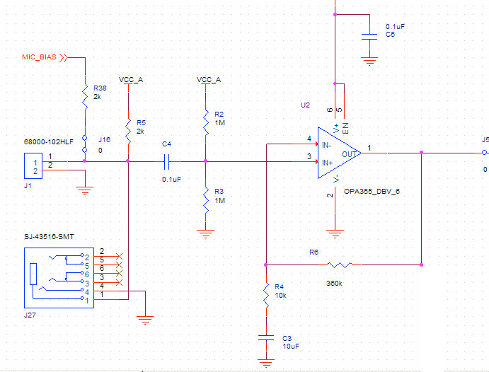
I'm still working on a circuit to hear my heartbeat. I've come a long way but it still doesn't sound as good as some example recordings I've heard. I was wondering if someone could spot something wrong in my input circuit. Currently I'm using an electret mic (CUI POM-2245L-C33-R) on a short wire inside the tube of a stethoscope (really close to the chest piece). The mic goes into my OPA350 opamp with a gain of around 30 like this. Sorry my VCC got cut off in this pic but it is 3.3V: enter image description here
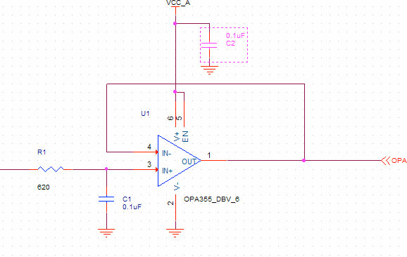
That feeds into a low pass filter at about 2.5k like this:
enter image description here

The output of the lowpass goes into a little codec DSP where I have a 250 tap low pass FIR filter at 220Hz. I've tried different frequencies. The DSP has some analog gain I can adjust, as well as digital gain, then it outputs to a pair of headphones. They seem to have enough bass response to hear the recordings I mentioned before.

Oh and all this is on a little 4 layer board I made, and I have decoupling all over. I can hear my heart beat, but it's a little muddied. I'm looking for ways to improve my design to get things clearer, maybe by getting better SNR. I've considered going full differential on the audio path, so diff output opamps into diff inputs on dsp. I've also tried increasing C4 to 10uF, and various different FIR filters. I've tried more gain but then it sounds like things are clipping. Could be noise though. Oh and I see some pro versions of this use piezo contact mics. I've tried that but I keep failing at it not sure why. I bought some piezo discs off of digi, and connected them across J1, with a 1Meg also across J1. I get sound but barely get hearbeat.

Anyway I thought I'd post what I had and see if anyone with more experience than me might spot a problem. I don't really know if I'm matching mic impedance to opamp input impedance properly.

\$\endgroup\$
2
  • \$\begingroup\$ Have you considered using a differential mic input stage ? After that it can be single-ended. Now you have effectively 1K bias for the mic, since you have the MIC_BIAS resistor and the AVDD resistor. That's a little low. Is there any effect if J16 is shorted or not? How many millivolts peak-to-peak do you get from the mic element? If you skip the filtering in the DSP, do you get a strong enough signal? If the signal is strong without the filtering, then obviously you need to improve the filtering. You could add some gain to the low-pass filter and perhaps make it elliptic. \$\endgroup\$
    – PkP
    Commented Nov 9, 2014 at 5:10
  • \$\begingroup\$ I had thought about it but haven't tried, maybe I'll give that a shot shouldn't be too hard to modify. I should have made the schematic more clear only J16 is a solder jumper that isn't installed. It gives me the option to remove R5 and use dsp to generate a mic bias. When I look at the output of the mic, the output of the opamp, or the output of the low pass I can't see the heartbeat signal. It just looks like noise to me, I can clearly see myself talking. It isn't until I go through the dsp that I can get anything. \$\endgroup\$
    – confused
    Commented Nov 9, 2014 at 18:43

2 Answers 2

2
\$\begingroup\$

Adding to @GeorgeHerold's answer:

  1. You need to include frequencies down to below 30Hz. Most of the energy in a typical heartbeat is between 30 and 40Hz. Given the cutoff for the highpass that @GeorgHerold computed, you are losing a good 15dB at the lower end.
  2. Try using a directional microphone instead of an omnidirectional. Directional microphones have two openings, one in front and one in back by the solder pads. I find I get much better results by installing a directional mic such that the front (where you normally speak into the mic) is inside the tube, with the port on the back of the microphone out in open air.

Actually, I don't use a stethoscope in my experiments. A simple plastic shell with a hole in it for the microphone works very well. What I've used for this is a plastic cap like you would use to close one end of a plastic water line. I had some laying around that are about 2" in diameter, and they work well.

I find that a directional electret microphone installed in a platic cap as described works well enough that I can capture heart sounds using nothing more than a PC or smartphone with no additional electronics - I can then do filtering, recording, or other processing digitally.
The PC soundcard has a 20dB boost on the mic input, but the smartphones don't. Since the cards use 16Bit sampling, you have plenty of headroom to digitally amplify the signal even without using the boost. If you resample from 44100 down to 400 or so, then you could probably gain the equivalent of a few bits

\$\endgroup\$
1
\$\begingroup\$

A link to the mic would help. I'm confused by R5 and R38. (as PkP asked.) And your coupling cap C4 looks small. There will be an RC high pass made by C4 and R38//R5. That's about ~1kHz so you are losing signal there. So I'd make both bias resistor and C4 bigger. (and tell us what R5 is all about?) Do you have a 'scope and function generator? One way to look at the frequency response of your circuit is to disconnect the mic and feed a small signal into the input. (Or use a spice simulation.) I might try a higher order LP filter at perhaps a lower frequency. (What frequencies are you interested in?) ... and maybe even another gain stage. Get rid of as much of the "out of band" noise as you can before you put the signal into your DSP.

\$\endgroup\$
3
  • \$\begingroup\$ Here are two links to the mic: puiaudio.com/pdf/POM-2245L-C33-R.pdf media.digikey.com/pdf/Data%20Sheets/Projects%20Unlimited%20PDFs/… I hadn't considered that R5 was part of the high pass filter. R5 I was using as my bias resistor for the mic, R38 is an option if I bridge J16. It allows me to use the DSP's mic bias output if I want to. I'll definitely try your suggestion on increasing the bias resistor and C4. I don't have a good signal generator at home maybe I have on at work I can borrow, and I'll try your suggestion on that. \$\endgroup\$
    – confused
    Commented Nov 9, 2014 at 18:44
  • \$\begingroup\$ My frequency of interest is 20-220Hz, with I think most of my energy at around 100Hz. Oh and I do have 4 more optional gain stages on my board, but they were just overdriving when I tried them before. \$\endgroup\$
    – confused
    Commented Nov 9, 2014 at 18:49
  • \$\begingroup\$ @confused, Hmm it'd be nice if they showed you the response below 50Hz, be nice to see where it dropped off. Re: bias resistors, as far as the signal is concerned you should consider the power supply rails as being the same as ground. (Think about a big cap to ground on the PS rail, if nothing else.) \$\endgroup\$ Commented Nov 9, 2014 at 23:05

Your Answer

By clicking “Post Your Answer”, you agree to our terms of service and acknowledge you have read our privacy policy.

Not the answer you're looking for? Browse other questions tagged or ask your own question.