0
\$\begingroup\$

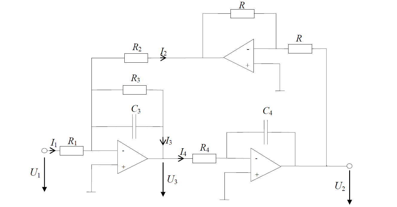
I would like to find transfer function between input signal \$U_1\$ and output signal \$U_2\$. So, I know how to find the transfer function of each op-amp, for example,

1 transfer function: $$\frac{v_o}{v_i} = -\frac{R_3}{R_1}\frac{1}{1+R_3C_3 s}$$ 2 transfer function: $$\frac{v_o}{v_i} = -\frac{1}{C_4 s R_4}$$ 3 transfer function: $$\frac{v_o}{v_i} = \frac{R_2}{2R}$$

Is that correct way to find $$G(s)=\frac{U_2}{U_1}$$? How can I do it?

\$\endgroup\$
1
  • \$\begingroup\$ Are sure about the direction of the tension arrows ? \$\endgroup\$
    – R Djorane
    Commented Nov 12, 2014 at 15:39

3 Answers 3

2
\$\begingroup\$

For my opinion, the simplest solution makes use of the classical feedback formula from H. Black:

$$\frac{V_2}{V_1}=\frac{H(s)}{1-LG}$$

with:

  • \$H(s)=H_1(s)H_2(s)\$=Forward transfer function for an open loop (in our case: \$H_1=V_3/V_1\$ for \$R_2\$>>infinite and \$H_2=V_2/V_3\$.)
  • Loop gain \$LG\$=Product of all three transfer functions within the loop (with \$V_1=0\$ or \$R_1\$>>infinite).

Note that \$H(s)\$ is positive and the loop gain \$LG\$ must be negative (three inverting stages in series). The transfer functions of the three blocks are basic (inverting lowpass, inverting integrator, inverting amplifier).

\$\endgroup\$
1
  • \$\begingroup\$ By the way - the circuit you call "amplifier" is one of the best-known state-variable filters: Universal filter block in Tow-Thomas topology. \$\endgroup\$
    – LvW
    Commented Nov 13, 2014 at 8:22
0
\$\begingroup\$

Anyway, all that you have to do is to calculate some of voltage and current equation with integration or derivate in the s domaine (Laplace).

For example: $$U_3 = R_4(I_4+I_3)$$ $$\frac{d_{U_2}}{d_t} = - \frac{1}{C4}(I3+I4)$$ so $$I_4+I_3 = - \frac{d_{U_2}}{d_t}C_4$$ $$U_3 = -R_4\frac{d_{U_2}}{dt}C_4$$ in S domain $$U_3(s) = -R_4\times C_4\times S\times U_2(s)$$ so $$G_2(s)=\frac{U_2(s)}{U_3(s)} = -\frac{1}{R_4\times C_4}$$ in the same way yo calculate \$G_1(s)=\frac{U_3}{U_1}\$ and you multipliate the two TF to have the G(s) because you have two Tf in cascade.

\$\endgroup\$
0
0
\$\begingroup\$

The problem here is that the feedback network also feeds your first opamp. Specificly, the current I2 flows trough your feedback network of R3 and C3 creating a higher (less negative) voltage at U3. So this said, your first equation is not complete, because you also need to take I2 into account.


I would start with the feedback network including the opamp, that produces current I2.

$$I_2 = -\frac{R_2}{U_2}$$

$$U_3 = -\left(\frac{U_{1}}{R_1} - I_2 \right ) \left( \frac{R_3}{1 + j\omega C_3 R_3}\right)$$

$$U_2 = -\left(\frac{U_3}{R_4} \right ) \left( \frac{1}{j\omega C_4} \right ) = -\frac{U_3}{j\omega C_4 R_4}$$

Then when you combine these, you get (if I don't make any typos or calculation errors): $$ U_2 = \frac{R_3}{-\omega^2 C_3 R_3 C_4 R_4} \left( \frac{R_2}{U_2} + \frac{U_1}{R_1} \right)$$

\$\endgroup\$

Your Answer

By clicking “Post Your Answer”, you agree to our terms of service and acknowledge you have read our privacy policy.

Not the answer you're looking for? Browse other questions tagged or ask your own question.