The 3V Solar Panel
A "3V Solar Panel" is the open-circuit voltage. In practice, the battery (1.2V) and the solar panel (3V, open circuit) will have to agree on where to operate. This is call the Q-point (Q = quiescent, latin for "being still" = equilibrium).
In the case of a weak panel and a comparative strong battery, the battery will win. The panel will be forced to operate at the battery voltage, driving current into the battery, charging it.
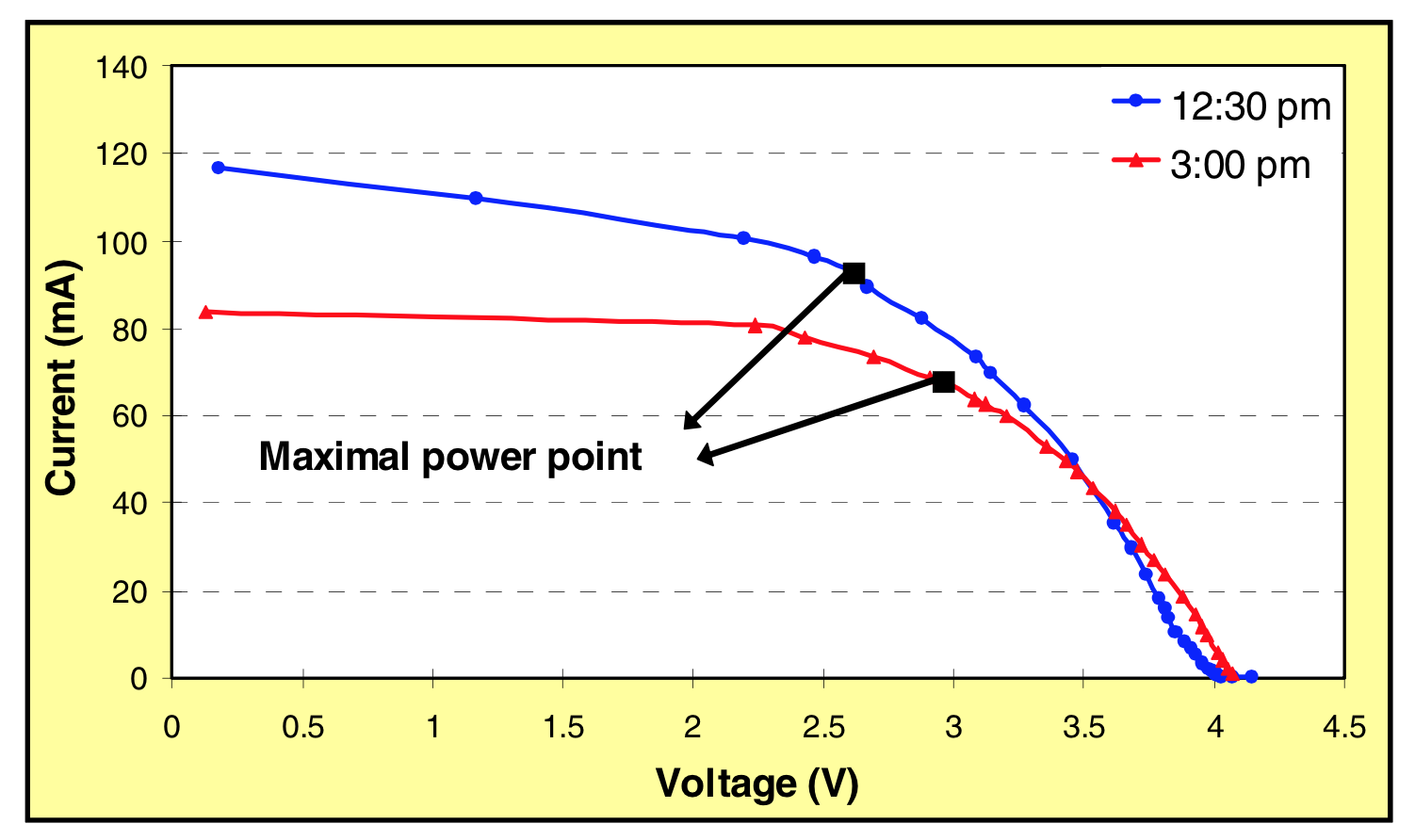
There will always be some form of directional element (usually a diode) between them to prevent the battery from "charging" the solar panel when the panel is insufficiently insolated (illuminated by the sun). This directional element will add a voltage drop further allowing the solar panel voltage to be closer to it's optimum power output point (typically about 60-80% of the open circuit voltage).
Here is data from a paper I wrote showing the location of the maximum power point for various levels of insolation on a small polycrystalline silicon solar panel.
 source: V. Raghunathan, A. Kansal, J. Hsu, J. Friedman, and M. Srivastava, "Design Considerations for Solar Energy Harvesting Wireless Embedded Systems"
The 1.2V LED
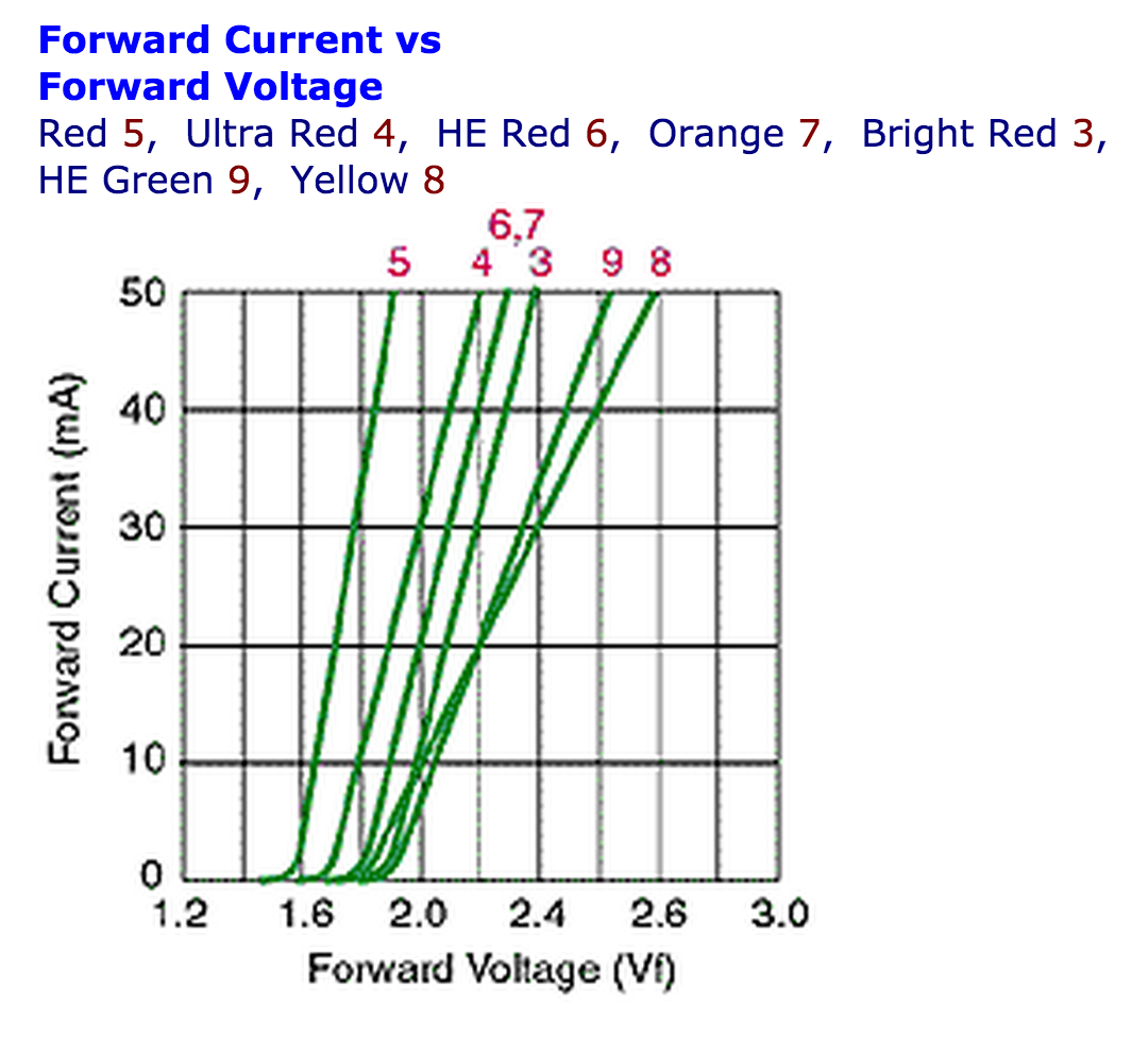
As you are, correctly, suggesting, it is very unlikely that the circuit drives the LED directly. You don't mention the LED's illumination color, but here's a broad overview of the various color chemistries:

As you can see, there isn't much output for any color-type at 1.2V. There is likely either a capacitive or inductive boost circuit in play that you simply haven't identified yet.
Further help
Post a schematic or, failing that, at a least several pictures of the device and we can try to help you identify the circuit you are dealing with.

 source: V. Raghunathan, A. Kansal, J. Hsu, J. Friedman, and M. Srivastava, "Design Considerations for Solar Energy Harvesting Wireless Embedded Systems"