0
\$\begingroup\$

I want to use MAX7219 (datasheet) to control bunch of RGB LEDs. With common anode LEDs I should be able to use up to 16 3-color bulbs in following configuration:
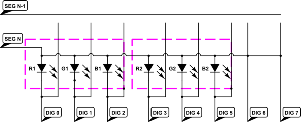
schematic

simulate this circuit – Schematic created using CircuitLab

There would be probably needed a resistor to protect the pins DIG 6 and DIG 7.

Now the RGB LED has drop voltage 3.2V on green/blue and 2.0V for the red color at 20mA. This would result in noticeable brightness difference of the LEDs. Is it possible to add 60Ω resistor to each red rail to fix the brightness of red color? The resistor is calculated from the voltage difference (3.2V-2.0V=1.2V) and driving current of 20mA. Given that only one LED is on at each time, this should be enough.

My goal is to control at least 16 RGB LED, in such way that I can control color of each bulb.

\$\endgroup\$
10
  • \$\begingroup\$ You ought to be controlling current into all the LEDs - driving with a fixed voltage is probably not recommended. See electronics.stackexchange.com/questions/141026/… - recently asked. \$\endgroup\$
    – Andy aka
    Commented Dec 1, 2014 at 12:52
  • \$\begingroup\$ The MAX7219 is constant current driver. But each color has different drop voltage, so the resistance has to be adjusted. \$\endgroup\$
    – jnovacho
    Commented Dec 1, 2014 at 14:46
  • \$\begingroup\$ Not normally - read the link I posted and note that LEDs should be driven with a constant current circuit. \$\endgroup\$
    – Andy aka
    Commented Dec 1, 2014 at 14:49
  • \$\begingroup\$ I still don't see how is that link related to my question. \$\endgroup\$
    – jnovacho
    Commented Dec 1, 2014 at 15:12
  • \$\begingroup\$ Constant current drivers don't care about series resistors. Series resistors are used with LEDs when driven from a constant voltage source. \$\endgroup\$
    – Andy aka
    Commented Dec 1, 2014 at 15:27

3 Answers 3

1
\$\begingroup\$

Now the RGB LED has drop voltage 3.2V on green/blue and 2.0V for the red color at 20mA. This would result in noticeable brightness difference of the LEDs

Why would it? A constant 20mA through the segment is a constant 20mA, regardless of the led Vf or Vs. The internal driver might dissipate more energy but thats mostly negligible.

If you already tested it and thing there is a higher current through the red leds, a silicon diode or two will bring the total Vf of the segment closer to the 3.2V, better than a resistor would, in a constant current driver setup.

\$\endgroup\$
2
  • \$\begingroup\$ You have to set the output current using Rset resistor. So I guess this works as reference value. Because each color has different voltage drop, the current will be 20 for G+B but 40 for R. At least that's what I understood from the datasheet. \$\endgroup\$
    – jnovacho
    Commented Dec 1, 2014 at 17:58
  • \$\begingroup\$ Doing some napkin math off table 11, the current for Red would be somewhere around 25mA, going by your logic. I believe the reference is independent of the actual voltage through the segments. If you wire it up and stick an ammeter between the red led and the segment pin, you would still only see 20mA. \$\endgroup\$
    – Passerby
    Commented Dec 1, 2014 at 18:09
1
\$\begingroup\$

In the end I have decided to use WS2812 led strip. It's an 5050 LED with integrated driver circuit and each LED in strip is individually addressable, which is much simpler solution for my needs.

\$\endgroup\$
0
\$\begingroup\$

The MAX7219 has a resistor that sets the output drive current for all LEDs connected to the chip. Because you likely need different currents for red, green and blue LEDs I'd consider using three chips. Chip 1 connects to blue, chip 2 to red and chip 3 to green. Now, each chip can be set to deliver the correct current to keep brightness similar between the three colours.

\$\endgroup\$
4
  • \$\begingroup\$ when the max7219 is designed for up to 64 leds, and cost 10 in single quantities. It seems wasteful to recommend three. \$\endgroup\$
    – Passerby
    Commented Dec 1, 2014 at 17:42
  • \$\begingroup\$ At worst two because green and blue are equally speced... \$\endgroup\$
    – Passerby
    Commented Dec 1, 2014 at 17:43
  • \$\begingroup\$ This would not work, since both chips would be driving the segment lines at the same time, and there is no way for them to coordinate. \$\endgroup\$
    – captncraig
    Commented Apr 12, 2022 at 19:32
  • \$\begingroup\$ Oh yes it would work. I'm not saying it can be done the same way as you envisage of course. \$\endgroup\$
    – Andy aka
    Commented Apr 12, 2022 at 20:19

Your Answer

By clicking “Post Your Answer”, you agree to our terms of service and acknowledge you have read our privacy policy.

Not the answer you're looking for? Browse other questions tagged or ask your own question.