7
\$\begingroup\$

I'm designing a PCB with a transceiver that has differential signal pins for rf. These differential signals travel to a balun, which transforms them into a single-ended signal (50-Ohm characteristic). This output goes to a on-board chip antenna, with a matching network at the interface between the 50-Ohm microstrip and the antenna.

Say that I have an arbitrary distance from the IC to the antenna. I can:

  1. Put the balun close to the IC, minimizing the length of the differential traces and having a longer single-ended trace, like so:

enter image description here

  1. Place it close to the antenna, running most of the signal path through the differential traces:

enter image description here

  1. (put it somewhere in between)

Which method is preferred? There are multiple transceivers on this board, and I suspect the differential traces radiate less. Is this true? Are there other considerations?

\$\endgroup\$
3
  • \$\begingroup\$ If its a commercial unit, someone will probably already have antenna etc. installed, running to 50 ohm coax. Having a 50 ohm unbalanced output on the equipment standardises the setup. If you make a custom setup for your own use, all bets are off... \$\endgroup\$ Commented Dec 5, 2014 at 0:48
  • \$\begingroup\$ Thanks, @AlanCampbell. In this case, it's an on-board chip antenna (50-Ohm matched), so no connector is needed. I edited my question to be more clear. \$\endgroup\$
    – bitsmack
    Commented Dec 5, 2014 at 1:29
  • \$\begingroup\$ Can you draw a schematic to more clearly illustrate the situation? \$\endgroup\$
    – Phil Frost
    Commented Dec 5, 2014 at 2:15

1 Answer 1

6
\$\begingroup\$

All else equal, the differential traces will radiate less. This is because their opposing electric fields cancel for distances "far" away, with "far" being relative to the spacing of the traces. Less radiation also means less opportunity to pick up or contribute noise to or from other components near the feedline, which may or may not be a concern for you.

Given this, it could make more sense to use differential lines for as much of the distance as possible.

However, to get the advantages of a differential feedline requires that there are no common-mode currents on the differential traces. If there are common-mode currents, then the differential microstrips are effectively just a fatter ordinary microstrip. Ostensibly the IC should drive the differential traces in such a way that there is no significant common-mode current, but you could check the datasheet to see if they have any suggestions. Differential traces are harder to route, so you have some design trade-off decisions to make.

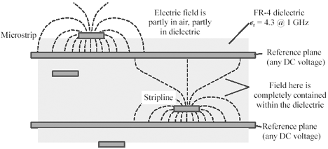
The reason microstrip radiates more is that the trace isn't fully enclosed, and so the electric field extends away some distance from the trace. Here's an image from High Speed Signal Propagation: Advanced Black Magic

enter image description here

This image also hints at another solution: stripline. Co-planar waveguides are another option which can be fabricated on a 2-layer board. Each of these helps to constrain the electric field to a smaller area, reducing radiation loss and increasing isolation. They are probably overkill for your application, but for instances where you need a single-ended transmission line and microstrip just isn't good enough, they are options.

\$\endgroup\$
1
  • \$\begingroup\$ Excellent, Phil, thank you. Also thanks for mentioning co-planar waveguides and striplines. On a side note: I keep finding references to Howard Johnson's books; I guess I'll have to go buy them :) \$\endgroup\$
    – bitsmack
    Commented Dec 5, 2014 at 13:14

Your Answer

By clicking “Post Your Answer”, you agree to our terms of service and acknowledge you have read our privacy policy.

Not the answer you're looking for? Browse other questions tagged or ask your own question.