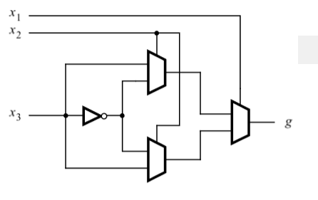
I would like to determine the number of transistors that will be used in the CMOS circuit below. Is there a specific formula for it?

I would like to determine the number of transistors that will be used in the CMOS circuit below. Is there a specific formula for it?

The above problem can be solved by using TG We have 3 inputs now for sake of less number of MOS to be used lets get \$x_1 x_2 x_3\$ in true logic as well as inverted logic
So MOS needed for 3 inverters is \$ 3 \times 2 = 6\$
now all we need are 3 TG to be implemented NOTE: since we already have inverted logic form of \$x_1 x_2 x_3\$ we don't need inverters again Thus to implement 3 TG we need \$ 3 \times 2 = 6\$ MOS
Thus total \$ 6 +\ 6=12 \$ MOS needed
What is guaranteed about the strength of the x3 input, and what are the output drive requirements? The most straightforward implementation using transmission gates would use two transistors for the inverter, two for inverters on x1 and x2, and four for each mux, for a total of 18. It would, however, pass through the x3 input directly without buffering in cases where the output state would match it. If x3 is weakly driven, that could be bad. Such problem would be best avoided by adding an extra inverter to that the muxes switch between once-inverted and twice-inverted x3.
Additionally, it may be possible to reduce the transistor count by building transmission gates that use only the NFET; that would probably require adding an inverter on the output of the circuit (since NFET-based transmission gates are not very good at outputting a logic "high"), but the two extra transistors required for the inverter would be offset by the elimination of six PFETs.