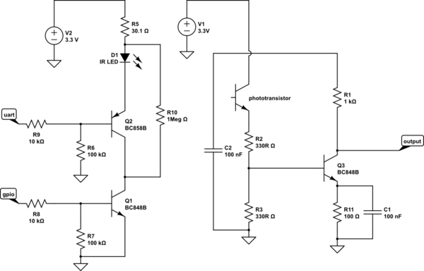
I'm trying to sense IR wave with a phototransistor circuit. The circuit operates well under DC operations (I mean 3V or 0V through inputs). However, if a square wave is supplied from UART input, propagation delay increases after some frequency due to bandwidth of phototransistor(I suppose). What should I consider to increase bandwidth? There is 1.5cm space between IR & phototransistor in vertical axis. LED draws about 15mA current when it conducts.
For example;
When 8kHz, %50 DC, square wave input is applied from UART pin, the DC of output decreases to 27% with about 20us propagation delay.
I've tried increasing the distance between IR & phototransistor to decrease photocurrent gain. Is it a good approach, or should I vary resistance values to decrease gain? Lowering the value of R2&R3 gave me better result; but, what other effects should I take into account?
Here are the datasheets:
bc848b: http://www.nxp.com/documents/data_sheet/BC848_SER.pdf
bc858b: http://www.nxp.com/documents/data_sheet/BC856_BC857_BC858.pdf
phototransistor: http://www.megasan.com/service/pdfhandler.ashx?fileid=3565

simulate this circuit – Schematic created using CircuitLab
edit: Problem has solved according to values of updated schematic. For square wave input with 3Vpp, 50%DC up to 9.6kHz has been tested. @4.8kHz -> DC: 45%, propagation delay: 10us @9.6kHz -> DC: 40%
