4
\$\begingroup\$

I've inherited an RF amplifier design (50MHz-1GHz) that uses an instrumentation amplifier to accept a DC voltage control signal. Neither myself nor my PI can explain why R8 and R18 are present. My guesses follow.
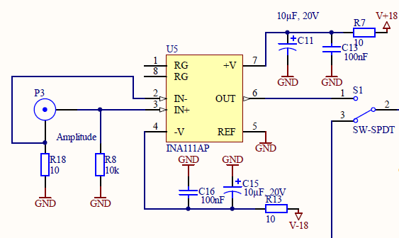
Instrumentation amplifier circuit

R8: Reading the spec sheet of related amplifiers, they say that the input bias current must have a DC path to ground for the amplifier to not float / saturate. This doesn't seem to be the case here: the input is just a coax cable with a DC control voltage on it. I think I'd need the 10k if I had a thermocouple, or transformer. But here it seems unnecessary, and makes the input impedance much lower.

R18: Why would you want your opamp to be referenced slightly above ground? Is this to compensate somehow for the offset voltage (which is 500uV max)?

I'm tempted to remove both to save PCB space, but this is a working design so I'm hesitant to make a change based on ignorance.

Thanks!

\$\endgroup\$

1 Answer 1

6
\$\begingroup\$

R8 and R18 serve an important function. They guarantee a zero volt input when the input coax isn't connected to anything. Without them, the inputs would float to unspecified (and probably unpleasant) levels. They do not try to reference the input measurably above ground. The INA111 has input bias currents of about 20 pA, so there is really no IR drop there.

R18 is not zero, just in case the cable is connected to a system with a ground slightly different than the INA111. Without it, such a connection could conceivably produce nasty ground loop currents.

\$\endgroup\$
2
  • 1
    \$\begingroup\$ So they are pulldown resistors, essentially? what about choice of resistor values, e.g. I can see 10 Ohms because you dont want to be too far from ground while operating, but why did they choose 10k vs 1M? It seems like 10k will lose much input impedance, and thus will draw current from the source. \$\endgroup\$
    – Paul L
    Commented Dec 31, 2014 at 20:49
  • 1
    \$\begingroup\$ You said it works to "accept a DC voltage control signal". I'd assume any control signal would have a fairly low impedance, being the output of a conditioning amp or maybe the output of a pot, so input impedance for this section shouldn't be a concern. \$\endgroup\$ Commented Dec 31, 2014 at 22:20

Your Answer

By clicking “Post Your Answer”, you agree to our terms of service and acknowledge you have read our privacy policy.

Not the answer you're looking for? Browse other questions tagged or ask your own question.