I have an 2.8" LCD that it's controller is ILI9325. I'm trying to use it. for start off, I have written a simple program. the program is this:
#include "stm32f10x.h"
#include "ILI9325.h"

int main(void)
{
    uint8_t b,c;

    Lcd_Configuration();
    Lcd_Initialize();
    Lcd_Clear(0xffff);
    Lcd_Clear(0x0000);
    Lcd_Clear(0xff00);
    for ( b = 0 ; b < 200 ; b++ )
    {
        for ( c = 0 ; c < 200 ; c++ )
        {
            DrawPixel( b , c , 0xffff );
        }
    }

    test_color();

    /* Infinite loop */
    while (1)
    {

  }
}
The ILI9325.h is:
#ifndef __ILI9325_H
#define __ILI9325_H

// ILI9320 or ILI9325
#define  ILI9325


#define ID_AM  110
extern u16 q;

//#define Delay //Display Delay//Immediately

#define Set_Cs  GPIO_SetBits(GPIOC,GPIO_Pin_8);
#define Clr_Cs  GPIO_ResetBits(GPIOC,GPIO_Pin_8);

#define Set_Rs  GPIO_SetBits(GPIOC,GPIO_Pin_9);
#define Clr_Rs  GPIO_ResetBits(GPIOC,GPIO_Pin_9);

#define Set_nWr GPIO_SetBits(GPIOC,GPIO_Pin_10);
#define Clr_nWr GPIO_ResetBits(GPIOC,GPIO_Pin_10);

#define Set_nRd GPIO_SetBits(GPIOC,GPIO_Pin_11);
#define Clr_nRd GPIO_ResetBits(GPIOC,GPIO_Pin_11);

#define Set_Rst GPIO_SetBits(GPIOC,GPIO_Pin_12);
#define Clr_Rst GPIO_ResetBits(GPIOC,GPIO_Pin_12);

#define Lcd_Light_ON   GPIO_SetBits(GPIOC,GPIO_Pin_13);
#define Lcd_Light_OFF  GPIO_ResetBits(GPIOC,GPIO_Pin_13);

typedef union
{
  u16 U16;
  u8 U8[2];
}ColorTypeDef;


void Lcd_Configuration(void);
void DataToWrite(u16 data);
void LCD_WR_REG(u16 Index,u16 CongfigTemp);
void Lcd_Initialize(void);
void Lcd_WR_Start(void);
void Lcd_SetCursor(u8 x,u16 y);
void Lcd_Clear(u16 Color);
void Lcd_ClearCharBox(u8 x,u16 y,u16 Color);
void DrawPixel(u16 x, u16 y, int Color);
void Lcd_SetBox(u8 xStart,u16 yStart,u8 xLong,u16 yLong,u16 x_offset,u16 y_offset);
void Lcd_ColorBox(u8 x,u16 y,u8 xLong,u16 yLong,u16 Color);
void test_color(void);

void Delay_nms(int n);
//u16 Read9325(void);

#endif
and the ILI9325.c is:
#include "stm32f10x.h"
#include "ILI9325.h"

u16 q;

/****************************************************************

PB8--PB15
PC0--PC7
PC8 --> Lcd_cs
PC9 --> Lcd_rs*
PC10 --> Lcd_wr
PC11 --> Lcd_rd*
PC12 --> Lcd_rst
PC13 --> Lcd_blaklight

*****************************************************************/

void Lcd_Configuration(void)
{
    GPIO_InitTypeDef GPIO_InitStructure;

    RCC_APB2PeriphClockCmd(RCC_APB2Periph_GPIOA|RCC_APB2Periph_GPIOB|RCC_APB2Periph_GPIOC, ENABLE);

    GPIO_InitStructure.GPIO_Pin = GPIO_Pin_8|GPIO_Pin_9|GPIO_Pin_10|GPIO_Pin_11|GPIO_Pin_12|GPIO_Pin_13|GPIO_Pin_14|GPIO_Pin_15;
    GPIO_InitStructure.GPIO_Speed = GPIO_Speed_50MHz;
    GPIO_InitStructure.GPIO_Mode = GPIO_Mode_Out_PP;
    GPIO_Init(GPIOB, &GPIO_InitStructure);

    GPIO_InitStructure.GPIO_Pin = GPIO_Pin_0|GPIO_Pin_1|GPIO_Pin_2|GPIO_Pin_3|GPIO_Pin_4|GPIO_Pin_5|GPIO_Pin_6|GPIO_Pin_7;
    GPIO_Init(GPIOC, &GPIO_InitStructure);

    GPIO_InitStructure.GPIO_Pin = GPIO_Pin_8|GPIO_Pin_9|GPIO_Pin_10|GPIO_Pin_11|GPIO_Pin_12;
    GPIO_Init(GPIOC, &GPIO_InitStructure);

    GPIO_InitStructure.GPIO_Pin =GPIO_Pin_13;
    GPIO_Init(GPIOC, &GPIO_InitStructure);
}


void DataToWrite(u16 data)
{
    u16 temp;
    temp = GPIO_ReadOutputData(GPIOB);
    GPIO_Write(GPIOB, (data<<8)|(temp&0x00ff));
    temp = GPIO_ReadOutputData(GPIOC);
    GPIO_Write(GPIOC, (data>>8)|(temp&0xff00));
}

void LCD_WR_REG(u16 Index,u16 CongfigTemp)
{
    Clr_Cs;
    Clr_Rs;
    Set_nRd;
    DataToWrite(Index);
    Clr_nWr;
    Set_nWr;
    Set_Rs;
    DataToWrite(CongfigTemp);
    Clr_nWr;
    Set_nWr;
    Set_Cs;
}

u16 CheckController(void)
{
    u16 tmp=0,tmp1=0,tmp2=0;
    GPIO_InitTypeDef GPIO_InitStructure;

    DataToWrite(0xffff);
    Set_Rst;
    Set_nWr;
    Set_Cs;
    Set_Rs;
    Set_nRd;
    Set_Rst;
    Delay_nms(1);
    Clr_Rst;
    Delay_nms(1);
    Set_Rst;
    Delay_nms(1);
    LCD_WR_REG(0x0000,0x0001);  //start oscillation
    Delay_nms(1);

    GPIO_InitStructure.GPIO_Pin = GPIO_Pin_8|GPIO_Pin_9|GPIO_Pin_10|GPIO_Pin_11|GPIO_Pin_12|GPIO_Pin_13|GPIO_Pin_14|GPIO_Pin_15;
    GPIO_InitStructure.GPIO_Speed = GPIO_Speed_2MHz;
    GPIO_InitStructure.GPIO_Mode = GPIO_Mode_IN_FLOATING;
    GPIO_Init(GPIOB, &GPIO_InitStructure);

    GPIO_InitStructure.GPIO_Pin = GPIO_Pin_0|GPIO_Pin_1|GPIO_Pin_2|GPIO_Pin_3|GPIO_Pin_4|GPIO_Pin_5|GPIO_Pin_6|GPIO_Pin_7;
    GPIO_Init(GPIOC, &GPIO_InitStructure);

    GPIO_ResetBits(GPIOC,GPIO_Pin_8);

    GPIO_SetBits(GPIOC,GPIO_Pin_9);

    GPIO_ResetBits(GPIOC,GPIO_Pin_11);

    tmp1 = GPIO_ReadInputData(GPIOB);
    tmp2 = GPIO_ReadInputData(GPIOC);

    tmp = (tmp1>>8) | (tmp2<<8);

    GPIO_SetBits(GPIOC,GPIO_Pin_11);

    GPIO_SetBits(GPIOC,GPIO_Pin_8);


    GPIO_InitStructure.GPIO_Pin = GPIO_Pin_8|GPIO_Pin_9|GPIO_Pin_10|GPIO_Pin_11|GPIO_Pin_12|GPIO_Pin_13|GPIO_Pin_14|GPIO_Pin_15;
    GPIO_InitStructure.GPIO_Speed = GPIO_Speed_50MHz;
    GPIO_InitStructure.GPIO_Mode = GPIO_Mode_Out_PP;
    GPIO_Init(GPIOB, &GPIO_InitStructure);

    GPIO_InitStructure.GPIO_Pin = GPIO_Pin_0|GPIO_Pin_1|GPIO_Pin_2|GPIO_Pin_3|GPIO_Pin_4|GPIO_Pin_5|GPIO_Pin_6|GPIO_Pin_7;
    GPIO_Init(GPIOC, &GPIO_InitStructure);

    return tmp;
}


void Lcd_Initialize(void)
{
    u16 i;
    Lcd_Light_ON;
    DataToWrite(0xffff);
    Set_Rst;
    Set_nWr;
    Set_Cs;
    Set_Rs;
    Set_nRd;
    Set_Rst;
    Delay_nms(1);
    Clr_Rst;
    Delay_nms(1);
    Set_Rst;
    Delay_nms(1);

/*
#ifdef ILI9325
    LCD_WR_REG(0x00e3,0x3008);
    LCD_WR_REG(0x00e7,0x0010);
    LCD_WR_REG(0x00ef,0x1231);  //Set the internal vcore voltage
    LCD_WR_REG(0x0001,0x0100);  //When SS = 0, the shift direction of outputs is from S1 to S720
#endif                          //When SS = 1, the shift direction of outputs is from S720 to S1.
#ifdef ILI9320
    LCD_WR_REG(0x00e5,0x8000);
    LCD_WR_REG(0x0000,0x0001);
    LCD_WR_REG(0x0001,0x0100);//S
    Delay_nms(10);
#endif
    LCD_WR_REG(0x0002,0x0700);//Line inversion
#if   ID_AM==000
    LCD_WR_REG(0x0003,0x0000);
#elif ID_AM==001
    LCD_WR_REG(0x0003,0x0008);
#elif ID_AM==010
    LCD_WR_REG(0x0003,0x0010);
#elif ID_AM==011
    LCD_WR_REG(0x0003,0x0018);
#elif ID_AM==100
    LCD_WR_REG(0x0003,0x0020);
#elif ID_AM==101
    LCD_WR_REG(0x0003,0x0028);
#elif ID_AM==110
    LCD_WR_REG(0x0003,0x0030);
#elif ID_AM==111
    LCD_WR_REG(0x0003,0x0038);
#endif
    LCD_WR_REG(0x0004,0x0000);
    LCD_WR_REG(0x0008,0x0207);
    LCD_WR_REG(0x0009,0x0000);
    LCD_WR_REG(0x000a,0x0000);
    LCD_WR_REG(0x000c,0x0001);
    LCD_WR_REG(0x000d,0x0000);
    LCD_WR_REG(0x000f,0x0000);

    LCD_WR_REG(0x0010,0x0000);
    LCD_WR_REG(0x0011,0x0000);
    LCD_WR_REG(0x0012,0x0000);
    LCD_WR_REG(0x0013,0x0000);
    Delay_nms(200);
    LCD_WR_REG(0x0010,0x17b0);
    LCD_WR_REG(0x0011,0x0137);
    Delay_nms(50);
    LCD_WR_REG(0x0012,0x0139);
    Delay_nms(50);
    LCD_WR_REG(0x0013,0x1700);
    LCD_WR_REG(0x0029,0x0000);
    LCD_WR_REG(0x002b,0x0000);
    Delay_nms(50);
#if   ID_AM==000
    LCD_WR_REG(0x0020,0x00ef);
    LCD_WR_REG(0x0021,0x013f);
#elif ID_AM==001
    LCD_WR_REG(0x0020,0x00ef);
    LCD_WR_REG(0x0021,0x013f);
#elif ID_AM==010
    LCD_WR_REG(0x0020,0x0000);
    LCD_WR_REG(0x0021,0x013f);
#elif ID_AM==011
    LCD_WR_REG(0x0020,0x0000);
    LCD_WR_REG(0x0021,0x013f);
#elif ID_AM==100
    LCD_WR_REG(0x0020,0x00ef);
    LCD_WR_REG(0x0021,0x0000);
#elif ID_AM==101
    LCD_WR_REG(0x0020,0x00ef);
    LCD_WR_REG(0x0021,0x0000);
#elif ID_AM==110
    LCD_WR_REG(0x0020,0x0000);
    LCD_WR_REG(0x0021,0x0000);
#elif ID_AM==111
    LCD_WR_REG(0x0020,0x0000);
    LCD_WR_REG(0x0021,0x0000);
#endif
    LCD_WR_REG(0x0030,0x0000);
    LCD_WR_REG(0x0031,0x0507);
    LCD_WR_REG(0x0032,0x0104);
    LCD_WR_REG(0x0035,0x0105);
    LCD_WR_REG(0x0036,0x0404);
    LCD_WR_REG(0x0037,0x0603);
    LCD_WR_REG(0x0038,0x0004);
    LCD_WR_REG(0x0039,0x0007);
    LCD_WR_REG(0x003c,0x0501);
    LCD_WR_REG(0x003d,0x0404);
    LCD_WR_REG(0x0050,0x0000);
    LCD_WR_REG(0x0051,0x00ef);
    LCD_WR_REG(0x0052,0x0000);
    LCD_WR_REG(0x0053,0x013f);
#ifdef ILI9325
    LCD_WR_REG(0x0060,0xa700);//G
#endif
#ifdef ILI9320
    LCD_WR_REG(0x0060,0x2700);//G
#endif
    LCD_WR_REG(0x0061,0x0001);//Enables the grayscale inversion of the image by setting REV=1.??????????????????????????????
    LCD_WR_REG(0x006a,0x0000);
    LCD_WR_REG(0x0080,0x0000);
    LCD_WR_REG(0x0081,0x0000);
    LCD_WR_REG(0x0082,0x0000);
    LCD_WR_REG(0x0083,0x0000);
    LCD_WR_REG(0x0084,0x0000);
    LCD_WR_REG(0x0085,0x0000);
    LCD_WR_REG(0x0090,0x0010);
    LCD_WR_REG(0x0092,0x0000);
    LCD_WR_REG(0x0093,0x0003);
    LCD_WR_REG(0x0095,0x0110);
    LCD_WR_REG(0x0097,0x0000);
    LCD_WR_REG(0x0098,0x0000);

    LCD_WR_REG(0x0007,0x0130);
#ifdef Immediately
    LCD_WR_REG(0x0007,0x0173);
#endif
       */
    i = CheckController();
    q=i;
    if(i==0x9325||i==0x9328)
    {
        LCD_WR_REG(0x00e7,0x0010);
        LCD_WR_REG(0x0000,0x0001);              //start internal osc
        LCD_WR_REG(0x0001,0x0100);
        LCD_WR_REG(0x0002,0x0700);              //power on sequence
        LCD_WR_REG(0x0003,(1<<12)|(1<<5)|(1<<4) );    //65K
        LCD_WR_REG(0x0004,0x0000);
        LCD_WR_REG(0x0008,0x0207);
        LCD_WR_REG(0x0009,0x0000);
        LCD_WR_REG(0x000a,0x0000);              //display setting
        LCD_WR_REG(0x000c,0x0001);              //display setting
        LCD_WR_REG(0x000d,0x0000);              //0f3c
        LCD_WR_REG(0x000f,0x0000);
        LCD_WR_REG(0x0010,0x0000);
        LCD_WR_REG(0x0011,0x0007);
        LCD_WR_REG(0x0012,0x0000);
        LCD_WR_REG(0x0013,0x0000);
        for(i=50000;i>0;i--);
        LCD_WR_REG(0x0010,0x1590);
        LCD_WR_REG(0x0011,0x0227);
        for(i=50000;i>0;i--);
        LCD_WR_REG(0x0012,0x009c);
        for(i=50000;i>0;i--);
        LCD_WR_REG(0x0013,0x1900);
        LCD_WR_REG(0x0029,0x0023);
        LCD_WR_REG(0x002b,0x000e);
        for(i=50000;i>0;i--);
        LCD_WR_REG(0x0020,0x0000);
        LCD_WR_REG(0x0021,0x0000);

        for(i=50000;i>0;i--);
        LCD_WR_REG(0x0030,0x0007);
        LCD_WR_REG(0x0031,0x0707);
        LCD_WR_REG(0x0032,0x0006);
        LCD_WR_REG(0x0035,0x0704);
        LCD_WR_REG(0x0036,0x1f04);
        LCD_WR_REG(0x0037,0x0004);
        LCD_WR_REG(0x0038,0x0000);
        LCD_WR_REG(0x0039,0x0706);
        LCD_WR_REG(0x003c,0x0701);
        LCD_WR_REG(0x003d,0x000f);
        for(i=50000;i>0;i--);
        LCD_WR_REG(0x0050,0x0000);
        LCD_WR_REG(0x0051,0x00ef);
        LCD_WR_REG(0x0052,0x0000);
        LCD_WR_REG(0x0053,0x013f);
        LCD_WR_REG(0x0060,0xa700);
        LCD_WR_REG(0x0061,0x0001);
        LCD_WR_REG(0x006a,0x0000);
        LCD_WR_REG(0x0080,0x0000);
        LCD_WR_REG(0x0081,0x0000);
        LCD_WR_REG(0x0082,0x0000);
        LCD_WR_REG(0x0083,0x0000);
        LCD_WR_REG(0x0084,0x0000);
        LCD_WR_REG(0x0085,0x0000);

        LCD_WR_REG(0x0090,0x0010);
        LCD_WR_REG(0x0092,0x0000);
        LCD_WR_REG(0x0093,0x0003);
        LCD_WR_REG(0x0095,0x0110);
        LCD_WR_REG(0x0097,0x0000);
        LCD_WR_REG(0x0098,0x0000);
         //display on sequence
        LCD_WR_REG(0x0007,0x0133);

        LCD_WR_REG(0x0020,0x0000);
        LCD_WR_REG(0x0021,0x0000);
    }
    else if(i==0x9320)
    {
        LCD_WR_REG(0x00,0x0000);
        LCD_WR_REG(0x01,0x0100);    //Driver Output Contral.
        LCD_WR_REG(0x02,0x0700);    //LCD Driver Waveform Contral.
        LCD_WR_REG(0x03,0x1030);    //Entry Mode Set.

        LCD_WR_REG(0x04,0x0000);    //Scalling Contral.
        LCD_WR_REG(0x08,0x0202);    //Display Contral 2.(0x0207)
        LCD_WR_REG(0x09,0x0000);    //Display Contral 3.(0x0000)
        LCD_WR_REG(0x0a,0x0000);    //Frame Cycle Contal.(0x0000)
        LCD_WR_REG(0x0c,(1<<0));  //Extern Display Interface Contral 1.(0x0000)
        LCD_WR_REG(0x0d,0x0000);    //Frame Maker Position.
        LCD_WR_REG(0x0f,0x0000);    //Extern Display Interface Contral 2.

        for(i=50000;i>0;i--);
        LCD_WR_REG(0x07,0x0101);    //Display Contral.
        for(i=50000;i>0;i--);

        LCD_WR_REG(0x10,(1<<12)|(0<<8)|(1<<7)|(1<<6)|(0<<4)); //Power Control 1.(0x16b0)
        LCD_WR_REG(0x11,0x0007);                                //Power Control 2.(0x0001)
        LCD_WR_REG(0x12,(1<<8)|(1<<4)|(0<<0));                    //Power Control 3.(0x0138)
        LCD_WR_REG(0x13,0x0b00);                                //Power Control 4.
        LCD_WR_REG(0x29,0x0000);                                //Power Control 7.

        LCD_WR_REG(0x2b,(1<<14)|(1<<4));

        LCD_WR_REG(0x50,0);     //Set X Start.
        LCD_WR_REG(0x51,239);   //Set X End.
        LCD_WR_REG(0x52,0);     //Set Y Start.
        LCD_WR_REG(0x53,319);   //Set Y End.

        LCD_WR_REG(0x60,0x2700);    //Driver Output Control.
        LCD_WR_REG(0x61,0x0001);    //Driver Output Control.
        LCD_WR_REG(0x6a,0x0000);    //Vertical Srcoll Control.

        LCD_WR_REG(0x80,0x0000);    //Display Position? Partial Display 1.
        LCD_WR_REG(0x81,0x0000);    //RAM Address Start? Partial Display 1.
        LCD_WR_REG(0x82,0x0000);    //RAM Address End-Partial Display 1.
        LCD_WR_REG(0x83,0x0000);    //Displsy Position? Partial Display 2.
        LCD_WR_REG(0x84,0x0000);    //RAM Address Start? Partial Display 2.
        LCD_WR_REG(0x85,0x0000);    //RAM Address End? Partial Display 2.

        LCD_WR_REG(0x90,(0<<7)|(16<<0));    //Frame Cycle Contral.(0x0013)
        LCD_WR_REG(0x92,0x0000);    //Panel Interface Contral 2.(0x0000)
        LCD_WR_REG(0x93,0x0001);    //Panel Interface Contral 3.
        LCD_WR_REG(0x95,0x0110);    //Frame Cycle Contral.(0x0110)
        LCD_WR_REG(0x97,(0<<8));  //
        LCD_WR_REG(0x98,0x0000);    //Frame Cycle Contral.


        LCD_WR_REG(0x07,0x0173);    //(0x0173)
    }
}


void Lcd_WR_Start(void)
{
    Clr_Cs;
    Clr_Rs;
    Set_nRd;
    DataToWrite(0x0022);
    Clr_nWr;
    Set_nWr;
    Set_Rs;
}


void Lcd_SetCursor(u8 x,u16 y)
{
    LCD_WR_REG(0x20,x);
    LCD_WR_REG(0x21,y);
}


void Lcd_Clear(u16 Color)
{
    u32 temp;

    Lcd_SetCursor(0x00, 0x0000);
    LCD_WR_REG(0x0050,0x00);
    LCD_WR_REG(0x0051,239);
    LCD_WR_REG(0x0052,0x00);
    LCD_WR_REG(0x0053,319);
    Lcd_WR_Start();
    Set_Rs;

    for (temp = 0; temp < 76800; temp++)
    {
        DataToWrite(Color);
        Clr_nWr;
        Set_nWr;
    }

    Set_Cs;
}


void Lcd_SetBox(u8 xStart,u16 yStart,u8 xLong,u16 yLong,u16 x_offset,u16 y_offset)
{

#if ID_AM==000
    Lcd_SetCursor(xStart+xLong-1+x_offset,yStart+yLong-1+y_offset);

#elif ID_AM==001
    Lcd_SetCursor(xStart+xLong-1+x_offset,yStart+yLong-1+y_offset);

#elif ID_AM==010
    Lcd_SetCursor(xStart+x_offset,yStart+yLong-1+y_offset);

#elif ID_AM==011
    Lcd_SetCursor(xStart+x_offset,yStart+yLong-1+y_offset);

#elif ID_AM==100
    Lcd_SetCursor(xStart+xLong-1+x_offset,yStart+y_offset);

#elif ID_AM==101
    Lcd_SetCursor(xStart+xLong-1+x_offset,yStart+y_offset);

#elif ID_AM==110
    Lcd_SetCursor(xStart+x_offset,yStart+y_offset);

#elif ID_AM==111
    Lcd_SetCursor(xStart+x_offset,yStart+y_offset);

#endif

    LCD_WR_REG(0x0050,xStart+x_offset);
    LCD_WR_REG(0x0051,xStart+xLong-1+x_offset);
    LCD_WR_REG(0x0052,yStart+y_offset);
    LCD_WR_REG(0x0053,yStart+yLong-1+y_offset);
}


void Lcd_ColorBox(u8 xStart,u16 yStart,u8 xLong,u16 yLong,u16 Color)
{
    u32 temp;

    Lcd_SetBox(xStart,yStart,xLong,yLong,0,0);
    Lcd_WR_Start();
    Set_Rs;

    for (temp=0; temp<xLong*yLong; temp++)
    {
        DataToWrite(Color);
        Clr_nWr;
        Set_nWr;
    }

    Set_Cs;
}


void Lcd_ClearCharBox(u8 x,u16 y,u16 Color)
{
    u32 temp;

    Lcd_SetBox(x*8,y*16,8,16,0,0);
    Lcd_WR_Start();
    Set_Rs;

    for (temp=0; temp < 128; temp++)
    {
        DataToWrite(Color);
        Clr_nWr;
        //Delay_nus(22);
        Set_nWr;
    }

    Set_Cs;
}


void Delay_nms(int n)
{

  u32 f=n,k;
  for (; f!=0; f--)
  {
    for(k=0xFFF; k!=0; k--);
  }

}
void DrawPixel(u16 x, u16 y, int Color)
{
    Lcd_SetCursor(x,y);
    Lcd_WR_Start();
    Set_Rs;
    DataToWrite(Color);
    Clr_nWr;
    Set_nWr;
    Set_Cs;
}
void DispPic240_320(const unsigned char *str)
{

    u32 temp;
    ColorTypeDef color;
    Lcd_SetCursor(0x00, 0x0000);
    LCD_WR_REG(0x0050,0x00);
    LCD_WR_REG(0x0051,239);
    LCD_WR_REG(0x0052,0);
    LCD_WR_REG(0x0053,319);
    Lcd_WR_Start();
    Set_Rs;

    for (temp = 0; temp < 240*320; temp++)
    {
        color.U8[1] =*(unsigned short *)(&str[ 2 * temp]);
        color.U8[0]=*(unsigned short *)(&str[ 2 * temp+1]);
        //DataToWrite(i);

        DataToWrite(color.U16);
        Clr_nWr;
        Set_nWr;
    }

//==============================
}
void test_color(void){
  u8  R_data,G_data,B_data,i,j;

    Lcd_SetCursor(0x00, 0x0000);
    LCD_WR_REG(0x0050,0x00);
    LCD_WR_REG(0x0051,239);
    LCD_WR_REG(0x0052,0);
    LCD_WR_REG(0x0053,319);
    Lcd_WR_Start();
    Set_Rs;
    R_data=0;G_data=0;B_data=0;
    for(j=0;j<50;j++)
    {
        for(i=0;i<240;i++)
            {R_data=i/8;DataToWrite(R_data<<11|G_data<<5|B_data);
            Clr_nWr;Set_nWr;}
    }
    R_data=0x1f;G_data=0x3f;B_data=0x1f;
    for(j=0;j<50;j++)
    {
        for(i=0;i<240;i++)
            {
            G_data=0x3f-(i/4);
            B_data=0x1f-(i/8);
            DataToWrite(R_data<<11|G_data<<5|B_data);
            Clr_nWr;
            Set_nWr;
            }
    }
//----------------------------------
    R_data=0;G_data=0;B_data=0;
    for(j=0;j<50;j++)
    {
        for(i=0;i<240;i++)
            {G_data=i/4;
            DataToWrite(R_data<<11|G_data<<5|B_data);
            Clr_nWr;
            Set_nWr;}
    }

    R_data=0x1f;G_data=0x3f;B_data=0x1f;
    for(j=0;j<50;j++)
    {
        for(i=0;i<240;i++)
            {
            R_data=0x1f-(i/8);
            B_data=0x1f-(i/8);
            DataToWrite(R_data<<11|G_data<<5|B_data);
            Clr_nWr;
            Set_nWr;
        }
    }
//----------------------------------

    R_data=0;G_data=0;B_data=0;
    for(j=0;j<60;j++)
    {
        for(i=0;i<240;i++)
            {B_data=i/8;DataToWrite(R_data<<11|G_data<<5|B_data);
            Clr_nWr;
            Set_nWr;}
    }

    B_data=0;
    R_data=0x1f;G_data=0x3f;B_data=0x1f;

    for(j=0;j<60;j++)
    {
        for(i=0;i<240;i++)
            {
            G_data=0x3f-(i/4);
            R_data=0x1f-(i/8);
            DataToWrite(R_data<<11|G_data<<5|B_data);
            Clr_nWr;
            Set_nWr;
        }
    }
    Set_Cs;
}
All pins of the LCD are connected to MCU and supply like this schematic:
VCC-------->3.3v
GND-------->GND
LED_VCC---->3.3v
LED_GND---->GND
Y(-)------->not connected
Y(+)------->not connected
X(-)------->not connected
X(+)------->not connected
IM0-------->not connected
RD--------->PC13
WR--------->PC10
RS--------->PC9
CS--------->PC8
RSt-------->PC12
(D1-D8)---->(PC0-PC7)
(D10-D17)-->(PB8-PB15)
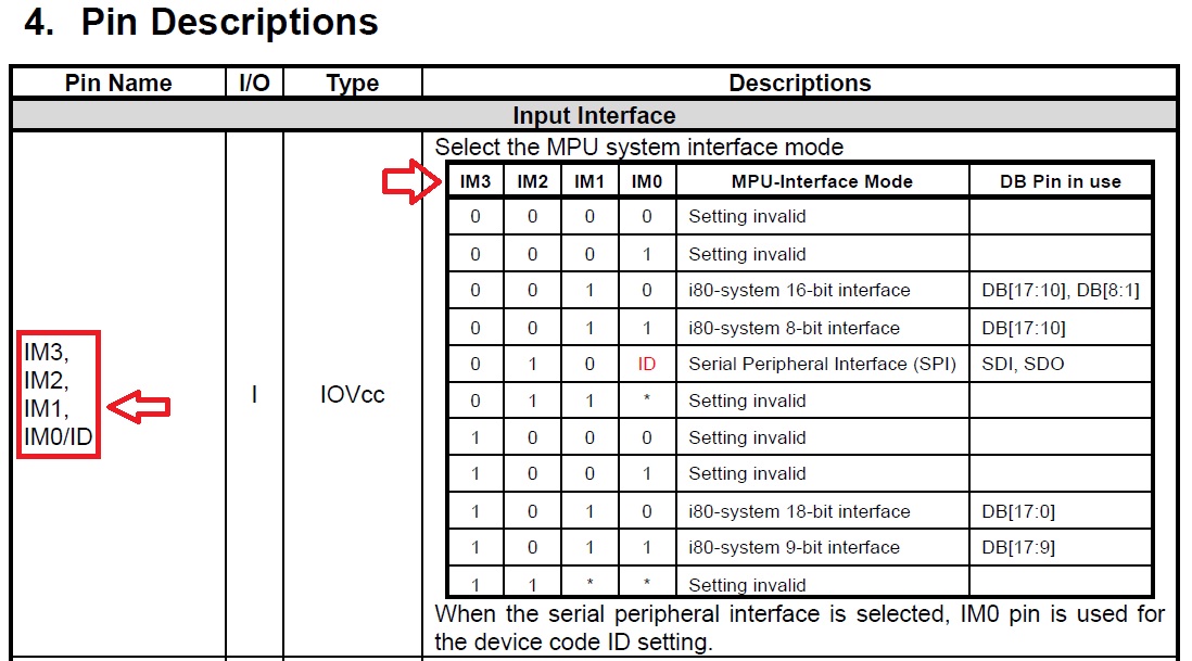
As you can see its interface is 16bit. for 16bit interface, if you see page 10 of ILI9325's datasheet you will see this:

And page 26:

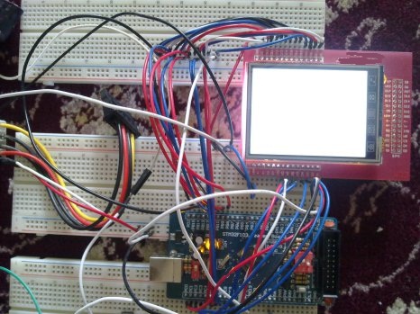
But lone IM[3:0] pin that I can see is IM0. by the way I think my circuit should work but when I trun on the circuit, lone thing that I can see is this:

Just a white background! damn it! What's the problem? in your opinion why doesn't my circuit(LCD) work?
