7
\$\begingroup\$

There's some basic flaw in my understanding of how LED's or diodes in general work so hope someone can help and forgive the simple question.

So generally when one has an LED in series with a resistor, it seems the LED will always have voltage drop corresponding of around 2V (more exact value can be read from datasheet). This means the voltage drop across the resistor will be the voltage drop of the source minus the 2V, and the resistor should be chosen simply to limit the current to, say, max 20 mA or whatever the datasheet says. But the relevant point here is that the size of the resistor won't impact the distribution of the voltage drops (over the resistor vs the LED). The LED has a "hard-wired" voltage drop and the resistor takes the rest.

So what if we have a different scenario, where a Zener diode is used to convert the voltage. So in this case, I have a Zener and a resistor in series, connected to the power supply. Let's say the Zener diode is 5V. It's connected "reverse" to take advantage of this reverse breakdown voltage. The resistor is such that the max current drawn can be 20 mA for the whole circuit. The circuit is seen here:
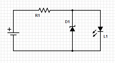
Circuit

The Voltage drop across the Zener should now be 5V (assuming the voltage source has a higher voltage than that) and the resistor limits the current.

Now the question is: What happens if I connect an LED in parallel with the Zener, without any resistor? A resistor shouldn't be necessary for current-limiting purposes since the resistor (in series with the Zener) is already limiting the current so we know there's never be an excess current. But since the LED is in parallel with the Zener, the voltage drop across it will be 5V, i.e. higher than before. So this is different from the case before where the circuit ensured the voltage drop across the LED was 2V. Here it seems it cannot do that, because there is only the LED to take the whole voltage drop.

Will this setup damage the LED? What value should I look for in the datasheet to find out what max voltage drop I can apply when there's no resistor? In the sheet I have for a typical LED, such a voltage is not listed under absolute max ratings. But I suppose I couldn't just put a drop across 1000V even if I assured the current was < 20 mA?

I'm also thinking if the wires will start acting as (small)resistors in series with the LED and somehow take the excess voltage.

\$\endgroup\$
2
  • \$\begingroup\$ One schematic worth 1000 words.. \$\endgroup\$
    – Eugene Sh.
    Commented Jan 20, 2015 at 22:49
  • \$\begingroup\$ Good point, added diagram \$\endgroup\$
    – Morty
    Commented Jan 20, 2015 at 22:57

3 Answers 3

9
\$\begingroup\$

The trick with diodes is they have an exponential I-V characteristic. This means that the current flowing through has an exponential dependence on the voltage, and past a certain point very small changes in voltage result in very large changes in current. The resistor basically serves as feedback, relating the voltage and current with a better-behaved linear relationship that is less sensitive to changes in voltage (linear instead of exponential). The exponential characteristic of a diode can be modelled as zero current until a thresold voltage is reached, then a constant voltage drop. Below the threshold, the diode is turned off ('in cutoff'), and above the threshold it will be forward biased.

If you put an LED in parallel with a zener diode, most likely no current will flow through the zener diode (it will be in cutoff) and all of the current will flow through the LED. This is because if you try to put more than 2v across an LED (assuming the forward voltage is 2v), you will get a very high current flow (amps, not mA) which the resistor will limit with a large voltage drop. So the circuit will end up stabilizing with 2V across both the LED and zener, but with little current flowing through the zener. You won't damage the LED so long as the resistor limits the current to something the LED can handle, but the zener will do nothing.

\$\endgroup\$
1
  • \$\begingroup\$ Thanks I see where I went wrong, also thanks to the other answers... my understanding was too simplistic. I think if I now work out the equations and think more carefully about it, it will be clear :-) \$\endgroup\$
    – Morty
    Commented Jan 20, 2015 at 23:22
3
\$\begingroup\$

The voltage and current across the diode are related in a non-linear fashion.

You could think of the diode as a voltage-dependant resistor.

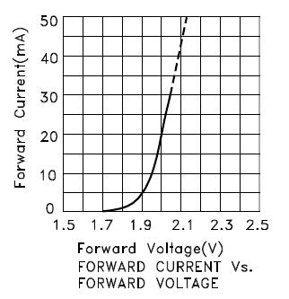
E.g. here is a graph of forward voltage vs current for an LED:

enter image description here

A resistor on the other hand would give a straight line starting from 0 with a slope of 1/R.

If you put other diodes or resistors in parallel with the diode then you have to solve a system of non-linear equations to get the actual current and voltage drop.

Using a fixed forward voltage drop for a diode is just a convenience. This value is either the current at which the forward voltage doesn't change much with increasing current (e.g. in the graph above when the line starts getting steep) or for LEDs, the recommended current for the rated brightness. E.g in the graph above if the current required for the rated brightness is 20mA the forward voltage will specified as 2.0V.

\$\endgroup\$
3
  • \$\begingroup\$ Hi thanks for your answer - but how is the equation solved (in the case with just a diode and a resistor in series) since there's two unknowns, the voltage drop over the diode and the current. Couldn't there be more solutions? Or I guess there's not I just don't see why... should probably work out and plot the equations or something. \$\endgroup\$
    – Morty
    Commented Jan 20, 2015 at 23:20
  • \$\begingroup\$ There is only one solution. The resistor gives you what is called a 'load line'. The load line is drawn on the IV curve with the same parameters - voltage across diode and current through diode - but it is determined by the resistor. For example, if you put a 50 ohm resistor in series with the diode with the IV curve in the figure above and use a 2.5 volt supply, the lode line would start at 50 mA and 0 volts (short across the diode) and extend to 0 mA 2.5 volts (open circuit). The intersection (solution) would then be around 25 mA and 2 V. \$\endgroup\$ Commented Jan 21, 2015 at 1:54
  • \$\begingroup\$ And generally the voltage drop over the diode is not an unknown, you know (more or less) what it is so you can replace the diode with a voltage source (assuming diode is forward biased). So that only leaves the current as an unknown. Basically, with diodes, there are only 3 operating modes to worry about: cutoff and forward and reverse bias. Take a guess on which mode it is in and solve. If you got it wrong (e.g. wrong current direction through voltage source representing the forward voltage drop) then try again with a different mode. \$\endgroup\$ Commented Jan 21, 2015 at 1:57
3
\$\begingroup\$

In your circuit, if you choose the resistor to allow 20 mA through the 5 volt Zener, then connect a 2 volt LED in parallel with the Zener, the LED will hold the voltage down to 2 volts, but the current will be much more than 20 mA, as the resistor now has to drop 3 volts more than in the no-LED case.

With the LED there, all the current will flow through the LED, and no current will flow through the Zener, as there will only be 2 volts across it.

The LED datasheet will show the typical voltage across the LED with some specified current. Often, there will be a graph showing how the voltage varies with current.

\$\endgroup\$

Your Answer

By clicking “Post Your Answer”, you agree to our terms of service and acknowledge you have read our privacy policy.

Not the answer you're looking for? Browse other questions tagged or ask your own question.