1
\$\begingroup\$

Background

I was considering making a temperature sensor from some NPN transistors. I read the Wikipedia page on Silicon Bandgap Temperature Sensors (can't use more than 2 links...) and this piece from Analog Devices, Inc., which I think neatly explains how two or more transistors can be used to sense temperature. Yet another reference is

The basic idea is that the base-emitter voltage V_BE can be related to temperature via.

V_BE = kT/q ln(I_C/I_s)

So, for two transistors.

V_BE1 = kT/q ln(I_C1/I_s1) V_BE2 = kT/q ln(I_C2/I_s2)

For two matched transistors, as in on an integrated circuit, I should have I_s = I_s1 = I_s2. Further, if I take the difference of these two.

V_BE1 - V_BE2 = kT/q ln(I_C1/I_s) - kT/q ln(I_C2/I_s)

Applying the fact that the difference between two logarithms ln(x) - ln(y) = ln(x/y),

V_BE1 - V_BE2 = kT/q ln( [I_C1/I_s] / [I_C2/I_s] )

And this equals

V_BE1 - V_BE2 = kT/q ln( [I_C1] / [I_C2] )

So, the difference in base-emitter voltages will give me temperature multiplied by a constant.

V_BE1 - V_BE2 = [k/q ln(I_C1/I_C2)] T

I made the following circuit. Since VB1 = VB2, VBE1 - VBE2 should equal VE1 - VE2, I measured the voltages VE1 and VBE2.

Schematic
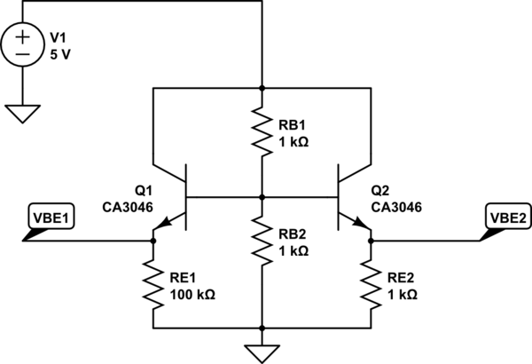
schematic

simulate this circuit – Schematic created using CircuitLab

Data

Now, with CH1 across RE1 and CH2 across RE2, my oscilloscope reads the following.

I also used the oscilloscope's MEASURE utility to find that VE1 was about 1.88 volts on average and VE2 was about 1.76 volts on average. I also measured this with my digital multimeter and found that the voltages fluctuate, but at one time I measured 1.909 volts across VE1 and 1.782 volts across VE2. The actual resistance values of RE1 and RE2 are 98.4 kiloohms and 1.01 kiloohm respectively.

So I_C1 = VE1/RE1 and I_C2 = VE2/RE2.

Problem

Now, if I go strictly by the equation

V_BE1 - V_BE2 = [k/q ln(I_C1/I_C2)] T

with k as Boltzmann's constant, q is the elementary charge (charge of an electron), and I_C1 and I_C2 are the collector currents of transistor 1 and 2 respectively, I should get a temperature reading for T.

T = (V_BE1 - V_BE2) * 1/[k/q ln(I_C1/I_C2)]

I get absurd temperature readings like -5415.135909660602 degrees Celsius or if I flip the values for I_C1 and I_C2, I get 5415.135909660602 degrees Celsius.

Is there something I'm missing? Thanks!

\$\endgroup\$
1
  • \$\begingroup\$ Jim Williams (probably) did a SUPERB bandgap development / what people get wrong paper long ago. SUPERB. Rushing ............. \$\endgroup\$
    – Russell McMahon
    Commented Jan 24, 2015 at 2:40

2 Answers 2

2
\$\begingroup\$

Your very first equation is wrong. If you check your link, it should be

Vbe = (kT/q) ln(ic/is)

When you correct your math, the temperature for your circuit is just about 300 K. Actually, assuming a current ratio of 100 gives 302.45 K, but that isn't quite right, and I'm too lazy to solve for the exact values. Plus, I doubt that your experimental error would support any more precision.

And, just as bit of advice, when you are working with measurements which have 3 significant digits, reporting a computation to 16 significant digits suggests very strongly that you have no idea what the limitations of your measurements are. Just a tip.

\$\endgroup\$
10
  • \$\begingroup\$ I am confused. What is the difference between what I wrote and what you wrote? V_BE = kT/q ln(I_C/I_s) versus Vbe = (kT/q) ln(ic/is) aside from underscores? The natural logarithm in both cases is not in the denominator. Regarding the computation, I just pasted the result from Google. I do understand significant figures, but thanks for the tip. \$\endgroup\$ Commented Jan 24, 2015 at 4:04
  • \$\begingroup\$ Also, the whole point of using two transistors is to eliminate I_s (is in your notation) because it is a function of temperature itself. \$\endgroup\$ Commented Jan 24, 2015 at 4:10
  • \$\begingroup\$ I also used I_E ~= I_C. \$\endgroup\$ Commented Jan 24, 2015 at 4:23
  • \$\begingroup\$ I did some math with the measured V_BE and I_C values, with k and q pulled from Google and I_s pulled from Intersil's SPICE model: intersil.com/content/dam/Intersil/documents/ca30/ca3046.mdl, using maxima, I got V_BE: 1.909$ R_E2: 98.4 * 10^(3)$ I_C2: V_BE / R_E2$ I_s: 10^(-15)$ k: 1.3806488 * 10^(-23)$ q: 1.60217657 * 10^(-19)$ float(solve(V_BE = (k*T/q) * log(I_C2/I_s),T)); -> [T = 935.178311906166] (that's in Kelvin). But this is waaaaay beyond room temperature. So I'm curious what you did exactly to get anywhere near room temperature. \$\endgroup\$ Commented Jan 24, 2015 at 4:36
  • \$\begingroup\$ "The natural logarithm in both cases is not in the denominator." Nonetheless, that's (apparently) how you calculated it. With q at 1.6 x 10^-19, k at 1.38 x 10^-23, and a current ratio of 100, I get 302.45 \$\endgroup\$ Commented Jan 24, 2015 at 4:40
0
\$\begingroup\$

You're basically running 100x more current in Q2 than Q1. You can do this with just diodes, and BJTs with collector=base act as diodes. So, remove RB2, short RB1. You'll get somewhat higher current used from the supply.

Now, your scope measurements are a little difficult, and there is basically a large offset that needs to be removed. So, exchange the positions of the resistors RE1/2 with the 'diodes', and basically measure the VBE difference between Q1 and Q2

Also -- you don'e even have to use 2 transistors -- just use 1 transistor, and measure with 100k, then measure again with 1k, and do the math above. You'll get the same answer, but likely even more accurately because you are using the same transistor, so there's no inherent offsets between the two devices.

\$\endgroup\$

Your Answer

By clicking “Post Your Answer”, you agree to our terms of service and acknowledge you have read our privacy policy.

Not the answer you're looking for? Browse other questions tagged or ask your own question.