3
\$\begingroup\$

I want to calculate the gain of the following circuit, but two different ways give different results.
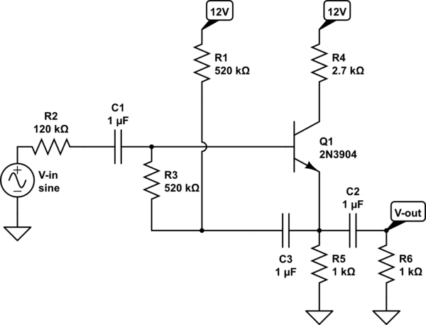
schematic

simulate this circuit – Schematic created using CircuitLab

First method:

(This method is explained in the answer by @AlfredCentauri to this similar question, if you want)

I assume a gain of near 1 for the emitter follower and just obtain the input impedance using the Miller theorem (boot strap), and obtain the output voltage from the voltage divider formed from the source resistance 120k and the input resistance of the circuit (which is near 50k), now the gain will be obtained about 0.3, which I believe is the correct answer.

Second method:

But when I just replace the small signal model of the transistor, I obtain something very near to zero (near 0.004) for the gain. I don't know whats wrong with my model:

In the ac model of the circuit with all of the DC sources grounded and capacitors short-circuited, the two \$1k\$ resistors are parallel and are shown as one 500 Ohm resistor in the circuit below. \$v_{\pi}\$ is the voltage across the \$r_{\pi}\$, as in the pie model of BJT. \$I_c\$ is obtained as \$1mA\$. Also \$V_T\$ is \$25mV\$ and thus \$r_{\pi}=2.5k\$ and \$g_m=1/25\$.
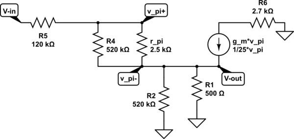
schematic

simulate this circuit

I simply omit the \$520k\$ resistor in parallel with \$r_{\pi}\$ and the one with the \$500\$ Ohm, and then I will have this equation: (KCL in the output node) (\$g_m=1/25\$)

\$ \frac{V_o}{0.5k}+\frac{V_o-V_i}{120k+2.5k \approx 120k}=g_m(v_i-v_o)\frac{2.5k}{2.5k+120k\approx 120k}\$

This would give approximately \$V_i=240V_o\$ or gain= 0.004.

\$\endgroup\$
2
  • 1
    \$\begingroup\$ I cannot justify the result of 0.004. Simple calculation error? I arrive at app. 0.7 (Simulation result app. 0.38). \$\endgroup\$
    – LvW
    Commented Jan 28, 2015 at 13:35
  • \$\begingroup\$ Because I forgot to mention: Simulation based on Spice model (3904); Quiescent current 1.4 mA; dynamic input resistance r,in=83kOhms. \$\endgroup\$
    – LvW
    Commented Jan 28, 2015 at 14:38

1 Answer 1

2
\$\begingroup\$

I think you just have an algebra mistake at the end. Starting from your last display equation: you can simplify the right-hand side to \$ (V_i - V_o) \frac{100}{120k} = \frac{V_i-V_o}{1.2k} \$. This is much bigger than the \$ \frac{V_i - V_o}{120k} \$ term on the left-hand side.

So you're left with \$ \frac{V_o}{0.5 k} = \frac{V_i - V_o}{1.2 k} \$, or more simply \$ 1.2 V_o = 0.5 (V_i - V_o) \$, giving \$V_o = 0.3 V_i \$. This agrees with the other analysis.

\$\endgroup\$
4
  • 1
    \$\begingroup\$ I would have worries about this circuit in a practical application. Both the DC base voltage and the source/input divider ratio will depend on beta, which is not usually that well controlled in the manufacturing process. Better raise RE to make the input impedance large, and set the quiescent point with a resistive divider that goes between Vcc and ground. \$\endgroup\$ Commented Jan 28, 2015 at 13:52
  • \$\begingroup\$ WOW, I can't believe this! I was stuck at this for more than two hours and repeated all parts of the calculation except the last part! Many thanks! \$\endgroup\$
    – user215721
    Commented Jan 28, 2015 at 13:53
  • 1
    \$\begingroup\$ No worries, I did the same thing! \$\endgroup\$ Commented Jan 28, 2015 at 13:55
  • 1
    \$\begingroup\$ I suppose, it is Vo=0.3Vi. Correct? \$\endgroup\$
    – LvW
    Commented Jan 28, 2015 at 14:44

Your Answer

By clicking “Post Your Answer”, you agree to our terms of service and acknowledge you have read our privacy policy.

Not the answer you're looking for? Browse other questions tagged or ask your own question.