The primary winding is your live feed to your iron and this has a small inductance possibly in the range of 10uH to 1mH but with a small steel nut it will act as a partial shorted turn as well as exhibiting the desired ferrous magnetic properties so I could envisage your primary magnetizing inductance being in the order of 1uH.
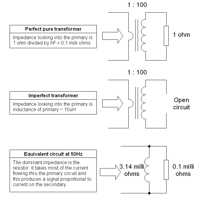
This will have a reactive impedance at 50Hz of 0.314 milli ohms. This in itself isn't a hindrance to making a CT because the whole idea about a CT is that the burden resistor divided by the turns ratio squared appears in parallel with the magentization inductance and, for a CT to work effectively, the equivalent primary impedance of the burden resistor must be significantly lower than the reactance.
Here is the development of the idea in circuit form: -
 Unfortunately this isn't going to happen with your design - you have a turns ratio of 2:1 and a burden value of 1.4 ohms. This burden, when referred to the primary looks like a resistance of 1.4/4 ohms i.e. 0.35 ohms - this is many times bigger than the magnetization reactance so your signal will be pitifully small.
If you wound 100 turns on a ferrite ring core this would be better - your primary inductance will be higher (due to the ferrite not acting like a shorted turn) so inductance might be 10uH for a small core and possibly 100uH for a bigger core. At 10uH the reactance is 3.14 milli-ohms - remember the reflected impedance of the burden must be significantly smaller than this.
With 1.4 ohms and 100 turns, the reflected burden on the primary is now 0.14 milliohms and this is looking better because it's starting to be significantly smaller than the 3.14 milliohms primary reactance.
Hope you get the general idea by now.
Most of the primary current is now passing thru the burden reflected thru to the primary (as opposed to the mag reactance) and for 1 amp drawn, I would expect to see about 14mV across the burden.

 Unfortunately this isn't going to happen with your design - you have a turns ratio of 2:1 and a burden value of 1.4 ohms. This burden, when referred to the primary looks like a resistance of 1.4/4 ohms i.e. 0.35 ohms - this is many times bigger than the magnetization reactance so your signal will be pitifully small.