1
\$\begingroup\$

I'm just starting to learn about electronics by working through Charles Platt's Make: Electronics book and I'm on experiment 14, which is a relaxation oscillator for an LED. I should note that in the schematic below, I wasn't able to figure out how to add a PUT (2n6027), so 'D4' is in fact a PUT.

When I increase R3, my intuition tells me that since I'm increasing the capacitor time constant, the capacitor should take longer to charge and thus I should see a longer time in between flashes. In practice, exactly the opposite happens. As I increase R3, the LED flashes more and more frequently. If I put in a 10K resistor for R3, the LED flashes so quickly that it appears to be staying on continuously (or the voltage across the anode of the PUT stays continuously above the gate voltage for some reason). Why does the frequency of the LED flashes increase, rather than decrease, when I increase R3?
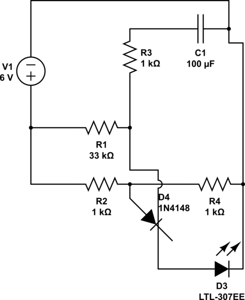
schematic

simulate this circuit – Schematic created using CircuitLab

\$\endgroup\$
1
  • 2
    \$\begingroup\$ Can you redo your schematic diagram so that it is more readable? \$\endgroup\$ Commented Feb 6, 2015 at 2:17

2 Answers 2

1
\$\begingroup\$

The basic operation can be seen more clearly if you first assume that C1 is shorted at time = 0. In that case you have a simple voltage divider created by R1 and R3, so increasing the value of R3 just increases the initial voltage at the anode connection. C1 then begins to charge and the gate trigger point (set by R2,R4) is reached much quicker.

Then because the charge time was very short only a small amount of charge accumulated on C1, so the discharge time (also the LED on time) is also very short.

Placing a diode in parallel with R3 may give you the result you expected (with cathode to C1). In that case R3 is nearly out of the circuit during C1 charging, but during C1 discharge R3 would extend the on time.

\$\endgroup\$
1
\$\begingroup\$

R3 controls the flash duration. It needs to be kept small in relation to R1. At 10K the voltage on the capacitor barely needs to increase at all to trigger the thyristor (since the resistor R3 is in series and the current through R1 also passes through R3).

To slow the flash rate, increase R1 or the capacitor.

\$\endgroup\$

Your Answer

By clicking “Post Your Answer”, you agree to our terms of service and acknowledge you have read our privacy policy.

Not the answer you're looking for? Browse other questions tagged or ask your own question.