0
\$\begingroup\$

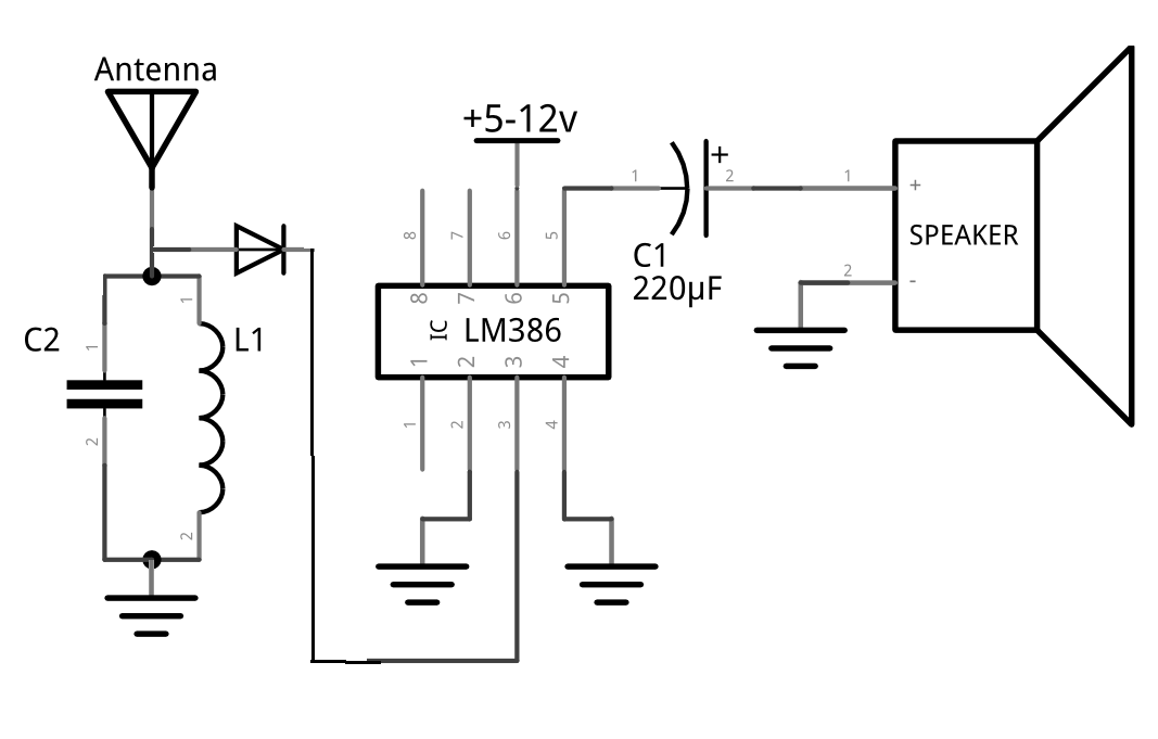
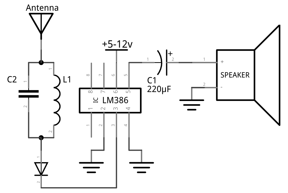
I've made two different circuits to receive RF using LM386 but they doesn't work. I've changed the values of C2 and L1 to change the frequency. I've also changed the gain but nothing happens.

The problem is that I hear a sound of noise or buzz from the speaker. When I touch Pin 3 (The input) or the Antenna, The sound become higher but anyway no radio station is received.

I've made a radio transmitter using a transistor before so, I turned it on. The receiver circuit received the song Which is the input of the transmitter. It receives no matter the values of the C2 and L1 of the Tank circuit so, I removed the tank circuit and connected the antenna directly to pin 3 and It also works receive the song.

Why it doesn't receive any radio station although it receive the signals that are transmitted by the transmitter circuit that I've made ?

What can I do to receive radio stations ? ( I live in area Where I can receive good radio stations AM and FM from my cell phone and Radio device )

here is the datasheet of the IC : http://www.ti.com/lit/ds/symlink/lm386.pdfenter image description here
enter image description here

\$\endgroup\$
6
  • 2
    \$\begingroup\$ @brhans - not really true. Though obviously off-label, using the LM386 for medium wave RF is a hack of long tradition in the ham world. The problem here is likely in the details, not the idea itself. \$\endgroup\$ Commented Feb 6, 2015 at 18:02
  • 2
    \$\begingroup\$ One might further note though that in this case it seems to be used to amplify a crystal radio, not for RF. Is the chosen diode suitable? \$\endgroup\$ Commented Feb 6, 2015 at 18:12
  • 1
    \$\begingroup\$ and here is the original project makerf.com/posts/… stipulating an IN34 as the diode (Germanium type) and the fact the builder of the circuit lived in a high apartment with a very strong AM signal. \$\endgroup\$ Commented Feb 6, 2015 at 19:11
  • 1
    \$\begingroup\$ Also note that your 220uF capacitor going to the speaker is shown reversed. The + terminal should connect to pin 5. \$\endgroup\$
    – Nedd
    Commented Feb 7, 2015 at 8:02
  • 1
    \$\begingroup\$ The LM380 is bad for HF crud and is on www.badbeetles.com. The 386 is a cousin and needs precautions taken .The old 380 would radiate into a ferrite rod and muck up AM broadcast reception. \$\endgroup\$
    – Autistic
    Commented Apr 8, 2016 at 23:45

2 Answers 2

5
\$\begingroup\$

What normally happens is that an AM antenna signal is amplified and tuned several times to create a much larger RF signal that is precisely pin-pointed on the channel the listener is trying to receive. Then it is fed thru a diode detector.

Without RF amplification (as a minimum of maybe 30dB or thereabouts) before the diode you are not going to have an RF signal that is not large enough to pass through a silicon diode so as to be rectified.

Non-ideal silicon diodes (as all silicon diodes are) pass very little signal below 100mV and your unamplified signal is going to be a few millivolts at best.

Back in the cats-whisker days of germanium diodes, strong signals could be picked up and detected this way so maybe try a germanium rectifier (or possibly schottky) and also remember the output of the diode needs a load resistor such as a couple of kohms - feeding it directly into a high impedance amplifier is also not going to help.

Also, using a diode like a 1N400x won't work either (even if the signal was substantial) because it's reverse recovery time is about 30us.

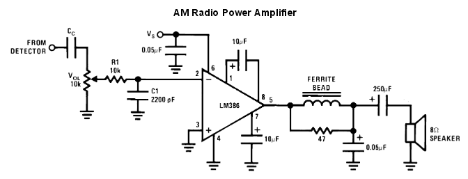
Also take note that the LM386 data sheet has this diagram: -

enter image description here

This circuit tells to you what to do after the detector stage. Of importance is R1 and C1 - these eradicate (largely) residual RF signals that may have crept through the detector.

\$\endgroup\$
1
  • 2
    \$\begingroup\$ , +1 for cats whisker reference. For all other folks, you might also search for "galena crystal". \$\endgroup\$
    – Marla
    Commented Feb 9, 2015 at 23:20
5
\$\begingroup\$

1) The first schematic is not correct, the second one is close to being correct.

2) The combination of C2 & L1 have to be resonant at your desired receive frequency.

3) The cathode of the diode (connected to pin 3 of the chip) needs both a pull-down resistor to ground and a small capacitor to filter out the received RF. I'd start with 10k and 1nF but you may need to experiment.

4) This circuit will receive AM signals, not FM. It should work well for the AM broadcast band of 560 KHz through 1.6MHz.

5) You may need to increase the gain of the LM386. Read the datasheet to learn how to do this.

\$\endgroup\$

Your Answer

By clicking “Post Your Answer”, you agree to our terms of service and acknowledge you have read our privacy policy.

Not the answer you're looking for? Browse other questions tagged or ask your own question.