0
\$\begingroup\$

I wish to use a simple way to turn on-off a 4 wire cpu fan using a digital output of the Arduino board. Since even with PWM=0 the fan works at 30% of the full speed, i have to find a way to cut off the power of the fan.

I came across some tutorials describing the optocoupler 4N25, so I decided to give it a try. For that purpose I didn't use the Arduino itself, but two separate powers of 5V and 12V.

The schematic shows exactly what I did first, and it worked fine. The LED was turning on and off accordingly to the switching of the left hand cirquit.
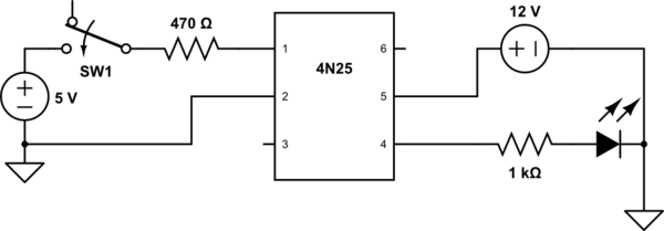
schematic

simulate this circuit – Schematic created using CircuitLab

After that I tried to connect the two wires of the fan (ground and power) in the (4) and (5) pins of the optocoupler, but the fan failed to respond to the commands of the switch, actually it didn't start at all. I guess that I miss something there.

I also tried to ground pin 6 (ground) with no success.

This is the type of the fan I am using: http://www.formfactors.org/developer/specs/REV1_2_Public.pdf

Any suggestions would be appreciated

Thank you in advance

\$\endgroup\$

2 Answers 2

2
\$\begingroup\$

Expanding on what Peter mentions above, this is the information you need to be concerned with from the datasheet of that device.

enter image description here

Notice that the output collector current shall be no more than 50mA continuous. As Peter stated, there is no way this device will directly drive the fan. What you want is the output of the 4N25 driving the gate of a FET or BJT that has the capacity to pass 1-2A of current, as suggested.

NB: The forward current of the LED between pins 1 and 2 has a forward current of 60mA max. You should take careful measures if you want to drive this device directly, as most controller pins can source/sink at most 20mA or so. Again, you should drive the gate of a FET from the controller which in turn drives the integrated LED. Otherwise you run the risk of damaging your controller.

\$\endgroup\$
1
  • \$\begingroup\$ I thank you both for your quick response. Finally I gave a try to the L293B motor driver (Imax.=2A) and it seems to work fine. \$\endgroup\$ Commented Feb 14, 2015 at 23:59
2
\$\begingroup\$

With 10 mA LED current, the 4N25's current transfer ratio is 20% minimum - that would give 2 mA throught the output transistor.

The specs for the fan call for 1 - 2 Amps - there is no way the 4N25 can directly drive the fan.

You need to have the opto drive a FET that can handle the 2 Amps the fan may want on starting.

\$\endgroup\$

Your Answer

By clicking “Post Your Answer”, you agree to our terms of service and acknowledge you have read our privacy policy.

Not the answer you're looking for? Browse other questions tagged or ask your own question.