0
\$\begingroup\$

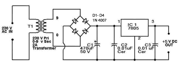
I have been searching for design equations for 5v regulated power supply but unable to figure it out. Please check the below circuit diagram enter image description here

Could anyone explain me why 470uf ? why not 2uf? how can we find out the capacitance value? when only Vrms is known? and also help me to understand the need for 0.01uf on both sides of 7805? Actually I want to connect this 5v output to 8051 micro controller. Any help is greatly appreciated.

\$\endgroup\$
0

2 Answers 2

1
\$\begingroup\$

You need to know your load current (if it's zero any capacitance would give you perfect DC even without a regulator). Textbooks give the following formula: Rload*C >> 1/f , i.e., the time constant of RC circuit formed by input cap and load must be much longer than AC wave period (~10 ms).

Filtered output of a rectifier looks like DC with ripple dV = Iload/2fC. Minimum voltage Vdc - dV must be higher than output voltage plus whatever the regulator is dropping, this will define the required capacitance, when Vdc and current are known.

\$\endgroup\$
2
  • \$\begingroup\$ I do not know the Iload value Iam connecting 8051 as output. is microcontroller current Iload? \$\endgroup\$
    – niko
    Commented Feb 19, 2015 at 18:45
  • \$\begingroup\$ For 8051 assume it to be equal 100 mA. 7805 drops like 3V so in order to get 5V out minimum input voltage to it must be 8V. \$\endgroup\$ Commented Feb 19, 2015 at 19:04
1
\$\begingroup\$

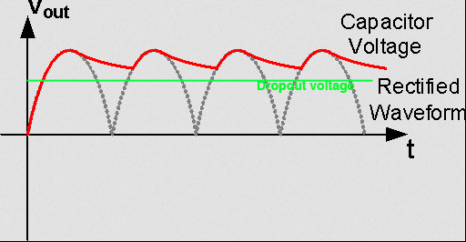
With a 50Hz input and full-wave rectifier, the capacitor can be thought of as only being charged at the peaks of the 100Hz output of the full-wave rectifier. It then discharges during the 10msec before the next peak occurs.

The ripple is thus 10ms * I/C where I is the current at the input to the regulator (call it the output current + 5mA) and C is the input filter capacitance.

So if the output current is 100mA, then the ripple (peak to peak) will be 2.1Vp-p. A larger value capacitor will reduce the ripple.

If you assume the transformer has 9V output at 230VAC in, then the peak voltage will be about 10V with full line voltage, and maybe 9V with line voltage a bit lower than nominal. The 7805 needs a couple of volts to work well (probably more like 1.6V at 100mA) so it should be fine even if the line voltage is a bit low. See here for some graphics as shown below. Put 2uF in there, and it will be dropping out of regulation every half cycle (100 times a second). Draw 1A rather than 100mA, and the 470uF will be woefully inadequate.
enter image description here

The 0.01uF ceramic on the input is to lower the impedance of the 470uF at high frequencies. You can leave that out if the regulator is close to the capacitor but it does no harm. The 0.01uF ceramic on the output lowers the regulator output impedance to higher frequencies (aka improve transient response)- you'll want more than that close to the 8051, 0.1uF to 1uF is good.
\$\endgroup\$

Not the answer you're looking for? Browse other questions tagged or ask your own question.