6
\$\begingroup\$

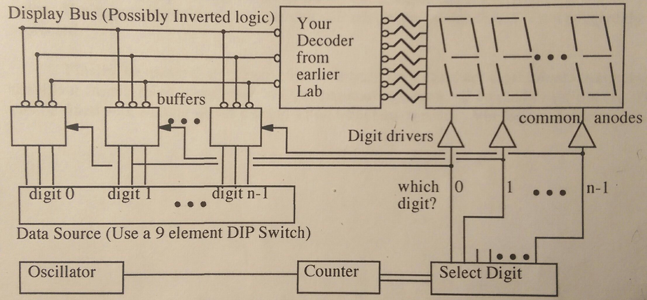
Frankly, I'm overwhelmed with this circuit that I have to start building in lab tomorrow. Last week we built an octal decoder that takes a 3-bit binary input from 000 to 111 and displays a unique character of our choosing on an LED display (common anode). It was all combinational logic and I understand it fairly well. Now we're expanding on the circuit and I don't understand a lot of the circuitry or how it works. I will briefly describe the assignment and then try to explain what I do and don't understand. Here is the schematic:

Circuit

Note that n=3 here.

The assignment:

We have to design and build a circuit that will display 9 bits of data on 3 separate 7 segment (common anode) displays. A DIP switch controls the three inputs of the decoder built last week. The three separate digit devices have corresponding segments wired together (e.g. a to a, b to b, etc.). The output only appears on one of the displays at a time, but if they are scanned fast enough they should all appear lit. For the multiplexing I have to use 7403 open collector logic. For each digit, we must design a transistor to function as a "high end digit driver" in order to source/sink appropriate current to light the digit adequately. We must design a counter circuit that produces the digit drive signals sequentially from right to left.

My Understanding:

Multiplexing

My prof described multiplexers essentially as electrical switches; they choose which signals to transmit. I think my biggest misunderstanding is rooted in what purpose the multiplexer serves in this circuit. Is the multiplexer represented in the schematic where it says "buffers"? Is that common? Originally, when we were using one display with the decoder, we didn't need a multiplexer. If the ultimate goal is to display the output on two additional displays, why couldn't we just wire the all the a's, b's, c's, etc. together? He also mentioned demultiplexing, but it's not clear if that's necessary here.

High End Digit Driver

The purpose of the transistor drivers are to supply/sink current to/from the LEDs, but it's unclear to what it's connected to electrically in terms of the emitter, collector, and base. If the drivers are simply sourcing or sinking current, why are they connected to the multiplexer?

Counter Circuit

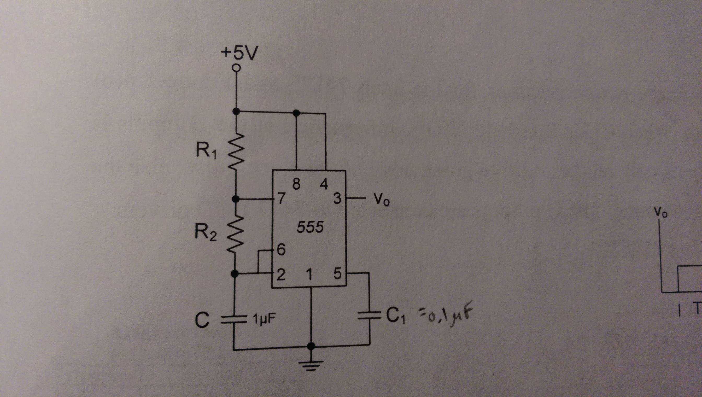
I've built a counter circuit once before using a 555 timer. This is the schematic:

Circuit #2

I believe I could use this circuit and tinker with the R values until I get a desirable output. However, what is considered a desirable output here? The procedure just says the counter circuit has to produce the digit drive signals - this seems vague.

\$\endgroup\$
3
  • 1
    \$\begingroup\$ The 555 design you show is only the oscillator section. You need a counter section connected to this. Using a single chip the counter could be created from a decade counter that clears itself after counting to 3. Using separate gates you might use 2 D-flipflops then decode the Q outputs to have 3 outputs that sequence as 0-1-2. \$\endgroup\$
    – Nedd
    Commented Feb 19, 2015 at 21:47
  • \$\begingroup\$ I don't have experience with using flip-flops, so I'd prefer to do it using the single chip. Can you direct me towards more information on using that method? \$\endgroup\$
    – JGill
    Commented Feb 19, 2015 at 21:53
  • 1
    \$\begingroup\$ Frequency should be aroud 300-500Hz. source: I'm in your class. \$\endgroup\$
    – user68260
    Commented Feb 21, 2015 at 1:22

4 Answers 4

3
\$\begingroup\$

I'll try to cover the parts of your question separately.

Multiplexing

Is the multiplexer represented in the schematic where it says "buffers"?

Nope! The multiplexer is the select digit part of the circuit. As you said, a multiplexer is an electrical switch: if I have \$n\$ "selector" inputs, I can choose from \$2^n\$ outputs. In your case, you have a two bit counter (because 1 bit isn't enough to count up to 2) which is connected to the "select" part of the multiplexer. The mux then sets one of its four outputs high, depending on what the counter is. If you make your counter reset as soon as it hits 3, then your multiplexer will set 0 high, then 1, then 2, and repeat this loop forever.

If the ultimate goal is to display the output on two additional displays, why couldn't we just wire the all the a's, b's, c's, etc. together?

When the mux has set digit 0 high, we only want to light up display 0 (and likewise for 1 and 2). If you wire the displays together, you can't control them all with different digits.

High End Digit Driver

The purpose of the transistor drivers are to supply/sink current to/from the LEDs, but it's unclear to what it's connected to electrically in terms of the emitter, collector, and base.

Look at a single digit driver. When its mux output is high, you want current to flow from your power supply into the LEDs; when the mux is low, you want to block that current. That means your which digit? output is probably connected to the base of the transistor, and setting it high allows current to flow from the collector to the emitter. Is that enough of a step in the right direction?

If the drivers are simply sourcing or sinking current, why are they connected to the multiplexer?

You'll have three drivers. You only want to turn on one at a time, and the multiplexer picks which one. They aren't "simply sourcing current", I guess - they're current sources that you can selectively turn on and off.

Counter Circuit

However, what is considered a desirable output here?

You want to count

0, 1, 2, 0, 1, 2, ...

so you'll need two wires (like I mentioned above). What parts do you have access to? What kind of counter circuits have you seen before?

As Nedd mentioned, you have a good oscillator set up - that'll be the input to your counter. Flip-flops would be a standard approach from there.

\$\endgroup\$
20
  • \$\begingroup\$ From what everyone's saying, it seems like 555 timer needs to be followed by a counter. Last semester we used them, but we weren't taught they worked; I think my current prof assumes that we do know how to use them. But I think I get the idea now: The 555 provides the pulse, and the counter uses that pulse to "talk" to the multiplexer. Is that right? The counter I have is a 74160. Will this work? Also, if the multiplexer isn't the "buffer" do you know what that might be? \$\endgroup\$
    – JGill
    Commented Feb 20, 2015 at 0:14
  • \$\begingroup\$ You have the right idea. The 555 provides the clock pulse, and the counter turns those into a (0, 1, 2) signal for the mux. \$\endgroup\$
    – Greg d'Eon
    Commented Feb 20, 2015 at 0:17
  • \$\begingroup\$ That counter looks pretty good. I only took a quick look at the datasheet - you might have to use some external circuits to make it jump from 3 back to 0. \$\endgroup\$
    – Greg d'Eon
    Commented Feb 20, 2015 at 0:25
  • \$\begingroup\$ I'll look into it. Is there a way I would be able to tell if it's working using a multimeter? \$\endgroup\$
    – JGill
    Commented Feb 20, 2015 at 0:27
  • 1
    \$\begingroup\$ If you don't have access to a scope, you can add LEDs to whatever lines yu want to monitor, and run the 555 clock real slow as Kynit suggests. \$\endgroup\$
    – tcrosley
    Commented Feb 20, 2015 at 0:36
2
\$\begingroup\$

I agree with you, and disagree with @Kynit: the multiplexer is the part marked "buffers" on your schematic. But more on that in a moment: let's walk through the circuit backwards, from the display to the oscillator.

I'm going not going to provide any schematics, and may be a little vague at times - as you're learning, I imagine it's best not to give too much away.

Display

As I understand it, your three 7-segment displays are common-anode, and have the cathodes of each segment wired to the corresponding segment in the other two displays. This implies that if you connect the three anodes to the positive supply and any given cathode to the negative supply (using appropriate current-limiting resistors, of course), then the corresponding segment would light up on all three displays.

This is obviously undesirable, because you want to be able to control each display independently. This is where the digit drivers come in.

Digit Drivers

Instead of directly connecting each of the three anodes to the positive supply, you can use three transistors (one on each display) as a switch to selectively connect a single display at any given time.

To do this, you'd connect each transistor's collector to the positive supply, the emitter to the display's anode via a current-limiting resistor, and use the base as the control input. Applying a positive voltage to the base turns the display on, connecting it to ground turns the display off.

Now you're able to decide which display will display any given digit. That's only half the battle though - you still need a way of taking the nine bits of input and selecting just the three bits corresponding to the display that's currently turned on.

Multiplexer

That's where the multiplexer comes in. Effectively, a multiplexer is just a device that takes multiple input signals and selects which one to output. Here, you want to split the nine-bit input into three three-bit inputs (i.e. digit 0, digit 1 and digit n-1 on your schematic), then use the multiplexer to place just one of those on the "display bus" at any given time.

You'll need a 3-to-1 multiplexer (you've got three inputs and one output), that is three bits wide (each signal is 3 bits). Fortunately, that's the same as having three parallel one-bit 3-to-1 multiplexers, for which schematics can easily be found online.

For example, bit 0 of digit 0, bit 0 of digit 1, and bit 0 of digit n-1 connect to the three inputs of the first multiplexer, and its output becomes bit 0 of your "display bus". Repeat twice more for bit 1 and bit 2.

So how do you decide which output is active at any time? The multiplexer has two extra "select" lines: applying logic 00 to these lines selects the first input, logic 01 the second, and logic 10 the third (with 11 unused). You may find designs with a slightly configuration (e.g. 01, 10, 11 instead of 00, 01, 10), but the first configuration is probably most common, and is what I assume in the rest of the discussion.

Great, so you can control which display is active, and which part of the input data it displays. But how to get it to cycle through the digits?

Counter

What you need now is some kind of cyclic counter that first selects display 0, then selects display 1, then display 2, back to display 0, display 1, and so forth.

This is known as a mod-3 counter, as it only has three possible output states: 0, 1, and 2. Digital counters are most easily built using a mod-2n construction, e.g. mod-2, mod-4, mod-8, etc, as this corresponds to a whole number of output bits (e.g. 1-bit, 2-bit and 3-bit respectively). Fortunately it's also easy to convert a mod-4 (i.e. 2-bit) counter with a "reset" input to mod-3 - simply tie the second output bit (which becomes high when the counter reaches 2) to the reset input. This means it will immediately return to 0 on the next cycle, instead of going to 3 first.

Again, schematics for the mod-4 counter can be found easily on the internet.

You can then tie this directly to your multiplexer - when the counter outputs 0 (logic 00) the input data for the first display is placed on the display bus, output 1 (01) selects the second display's data, and output 2 selects the third.

Again, this is only half the battle though - you can now cycle through the input data, but you still don't actively control which display is active.

2-to-4 Decoder

To control which display is active, you want to apply a positive signal to each display driver in turn. That is, when the counter outputs 0 (and the multiplexer has placed digit 0 on the display bus), you want the base of the first transistor to go positive, and the other two to go to ground. A similar argument applies for the other two display drivers. This is the purpose of your "select digit" block.

So, you basically want to take that two-bit output from your counter, and use it to select one of three lines depending on the counter value. The circuit that can do this is called a 2-to-4 decoder, which simply has two input lines and four outputs. When the input is 00, the first output is high and the others are low. When the input is 01, the second output is high and the others are low. When the input is 10, the third output is high and the others are low. And when the input is 11, the fourth output is high and the others are low.

You don't need four outputs, and your counter isn't ever going to output 11 anyway, so just use the first three outputs and connect them to your display drivers (ignoring the fourth output).

Note that your 3-to-1 multiplexer basically contains its own internal 2-to-4 decoder, so if you're implementing all of this in discrete logic you can actually simplify the multiplexer by using the output of the 2-to-4 decoder you're using for the digit selector - that's what seems to be implied on your schematic.

Again, schematics for 2-to-4 decoders are easily found online.

There's still one last thing you need though - some signal to cause the counter to cycle through its values.

Oscillator

Your 555 circuit is your oscillator, which simply produces a clock signal that drives the counter. The astable multivibrator circuit you show is exactly what you need, the only thing you need to figure out is the desired output frequency and duty cycle.

As mentioned by @EM Fields, the duty cycle probably isn't very important here, so a 50/50 cycle is a reasonable default.

For the frequency, you should try to refresh the whole display at least 30 times per second to avoid annoying flickering. Since you need to go through each of the three counter states to update the display once, that means your oscillator should run at at least 90 Hz, but it's worth going considerably faster than that just to be safe. On the other hand, during testing it can be useful to run the oscillator (very) slowly because then you can watch the digits as they change.

Given those values, there are formulas easily available that will tell you what size resistors to use.

A side note

Where the de-multiplexer comes into things (that your professor hinted about) is with the 2-to-4 decoder. As the name suggests, a de-multiplexer does the opposite of a multiplexer, taking a single input and switching it between one of several outputs. As such, the 2-to-4 decoder is basically just a one-bit 1-to-4 de-multiplexer, with its input permanently set at logic 1. This is why I disagree with @Kynit - what he/she describes as a multiplexer is, if anything, a de-multiplexer, and the actual multiplexer is elsewhere in the circuit.

I hope the above helps! If something doesn't quite add up, let me know and I'll be happy to sort it out.
\$\endgroup\$
11
  • \$\begingroup\$ Aha. You're right - I forgot what multiplexers are. This is more right than my answer. (ps: I'm a "he" :D ) \$\endgroup\$
    – Greg d'Eon
    Commented Feb 20, 2015 at 12:24
  • \$\begingroup\$ Appreciate the in-depth response! This helped immensely. I have several questions if you don't mind me asking. \$\endgroup\$
    – JGill
    Commented Feb 22, 2015 at 6:41
  • \$\begingroup\$ 1.) For the previous lab, when we made the decoder that displayed the output on a 7 segment display, there were only three inputs. Why do we have nine inputs here? Part of me says it’s because we have two more displays. However, as you said, all of the cathode segments of the displays are wired together – so I don’t see why we would need more inputs if the additional displays are really duplicates. Or do we need the inputs in order to control each display independently? If so, do the display segments still share common pins? \$\endgroup\$
    – JGill
    Commented Feb 22, 2015 at 6:43
  • \$\begingroup\$ Is the reason we’re multiplexing the signal so that we can rapidly and seamlessly choose what happens on the three displays without having to build the decoder section two additional times? \$\endgroup\$
    – JGill
    Commented Feb 22, 2015 at 6:47
  • \$\begingroup\$ 2.) I'm having problems with getting the counter working also. I'm using a 74193 4-bit counter (date sheet). The 555 output goes to the clock pin, while the clear pin is LOW and the countdown pin and load pins are HIGH. I hooked up an LED to observe the 555 output, and the flashing rate can be adjusted with a potentiometer. I then hooked up LEDs to observe the counter output and there is no flashing; only the D output is lit dimly. Nothing seems to change as I alter the 555 frequency either. \$\endgroup\$
    – JGill
    Commented Feb 22, 2015 at 6:47
1
\$\begingroup\$

The 555 provides only the oscillator, to produce the digit drive signals you also need a counter. One example is an MC14017. Use Q0, Q1, and Q2 as the inputs to your three digit drivers, then have the Q3 signal feedback to the Reset pin. So the output counts as 0,1,2,0,1.......

See the data sheet for other connection info:
http://www.onsemi.com/pub_link/Collateral/MC14017B-D.PDF

The circuitry after the counter could be considered a multiplexer as it selects one 3-bit data group at a time and sends it to the decoder.

\$\endgroup\$
4
  • \$\begingroup\$ So the 555 timer is only doing half the job? I believe I have 74160 counters from last semester. Would those work? We weren't really taught how they worked - it was more of a "connect this to this and that to that..." type of thing and we observed the end result. \$\endgroup\$
    – JGill
    Commented Feb 20, 2015 at 0:02
  • \$\begingroup\$ The 74160 while called a decade counter has a 4-bit binary output, it would count as 0000, 0001, 0010, 0011, ... up to binary 10 (1010), this could be used if you were to add the extra decoding logic to count as 001, 010, 100. Another chip option with decoded outputs is a CD4022. \$\endgroup\$
    – Nedd
    Commented Feb 20, 2015 at 4:51
  • \$\begingroup\$ I found out we actually have another counter. It's a 74193. \$\endgroup\$
    – JGill
    Commented Feb 21, 2015 at 23:35
  • \$\begingroup\$ The 74193 is also a binary output counter. \$\endgroup\$
    – Nedd
    Commented Mar 6, 2015 at 15:24
1
\$\begingroup\$

Nice project.

Starting at the tail end, with the oscillator, you're proposing using a 555 in its standard astable mode, so it'll free-run with an output frequency of:

$$f = \frac{1.46}{(R1+2R2)\ C} $$

and a duty cycle of

$$D = \frac{R2}{R1+2Rb}$$

For your application, duty cycle doesn't matter much, so make R1 equal to about 1000 ohms and work out R2 for the frequency you want with C1 equal to \$ 1\mu\$F, as you've shown.

Next, you need to be able to select one digit at a time out of a sequential recurring select cycle (that's where the multiplexing comes in) and, all at once, light up the segments you've selected for that digit with its DIP switch.

In order to do the multiplexing properly, you need to select one digit's common anode at a time, and your oscillator driving something like a 4017 will get you the basic timing, but not the drive.

So far so good?

\$\endgroup\$
5
  • \$\begingroup\$ We've used the 555 timer as a pulse generator in one other project, but it was more of a tool as we were more focused on other aspects of the circuit. However, I do recall the output frequency and duty cycle. But how do we know what the frequency should be in this application? I understand that the timer generates a window during which pulses will be allowed to pass, but I'm a little confused where to go from there. \$\endgroup\$
    – JGill
    Commented Feb 19, 2015 at 23:50
  • \$\begingroup\$ @JGill The frequency just needs to be fast enough that your eye doesn't see any flicker. That's about 25 Hz (movie film used to run at 24 frames/sec). Since you have three digits, and you have to "visit" each one, the minimum should be 75 Hz or so. I'd double that and make it around 150 Hz. \$\endgroup\$
    – tcrosley
    Commented Feb 20, 2015 at 0:39
  • \$\begingroup\$ @tcrosley, thanks, that makes sense. I just have to figure out how to rig it up with a counter now. Just out of curiosity, what would be the consequence of a frequency set at the extremes? Too low and we would see each display light up sequentially? But is there a consequence of a overly high frequency? \$\endgroup\$
    – JGill
    Commented Feb 20, 2015 at 0:49
  • \$\begingroup\$ @JGill Erroring on the high side of the frequency shouldn't have any noticeable effect. I was mostly trying to set a minimum. If you keep it around 150-200 Hz, it will be easier to adjust downward to 1 Hz or so with a pot. If you set it up for 1 KHz, it would be harder to adjust down so low. \$\endgroup\$
    – tcrosley
    Commented Feb 20, 2015 at 1:35
  • \$\begingroup\$ @tcrosley, I've gotten everything to work except the multiplexer. Using a regular multiplexer I get what I need to do, but I have to use 7403 open-collector NAND gates as the MUX. More details here. \$\endgroup\$
    – JGill
    Commented Feb 27, 2015 at 16:23

Your Answer

By clicking “Post Your Answer”, you agree to our terms of service and acknowledge you have read our privacy policy.

Not the answer you're looking for? Browse other questions tagged or ask your own question.