3
\$\begingroup\$

Quick question: are normally-open contactors (which I assume are simply high breaking capacity relays) virtually safe from failing closed?

I want to cut off a 400V 3-phase supply using an emergency stop, and I have 2 options:

  1. Use a 3-pole emergency stop, and wire the three phases to that button. I don't like the idea of 400V being so close to the user's hands.
  2. Wire the contacts of a 3-pole normally-open contactor on the supply line, and wire the emergency stop on the 230V coil.

Three phase is used for heating, not for a giant chainsaw, but the emergency button should still do its job should it be pressed. So is option 2 commonly accepted, and safe enough for an end product? Any norms stating this on which I could rely?

Edit implementing the answer

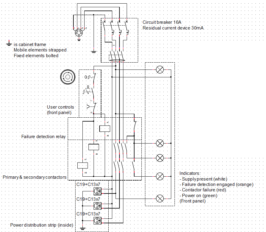
I am quite keen on the idea of forcing the user to fix a failure in the redundant system, but I'm trying to limit the number of components as well. Is this a good comromise? I found this contactor, which has 1NC and 1NO auxiliary contacts that we can use.

Since the current in the coils is already very small compared to the switches capability, I made them single pole, if that is acceptable.
enter image description here

In particular, I'm not sure whether there is a possibility that the auxiliary contacts do not follow the main contacts (meaning the main contacts may fail closed or welded without the auxiliary contacts staying open when normally closed), could you confirm?

\$\endgroup\$
11
  • 3
    \$\begingroup\$ I've seen relays with one or more of their supposedly normally open contacts 'welded' together ... But these may have been under-spec'ed to start with. \$\endgroup\$
    – brhans
    Commented Feb 25, 2015 at 15:26
  • 1
    \$\begingroup\$ I have seen 30A power relays with fake UL marks weld closed (on). Made quite a mess when they did that (destroyed the product). \$\endgroup\$ Commented Feb 25, 2015 at 15:37
  • \$\begingroup\$ Ditto - seen high current sparks weld contacts permanently together. \$\endgroup\$
    – bigjosh
    Commented Feb 25, 2015 at 15:40
  • \$\begingroup\$ You always have a miniscule chance that the contacts will weld together or there will be a mechanical failure inside the relay/contactor. But of course even a mechanical switch has this danger. \$\endgroup\$
    – Hot Licks
    Commented Feb 25, 2015 at 20:09
  • \$\begingroup\$ I understand trying to reduce the parts count - don't rube-goldberg any more than you have to - but your additional diagram has a some issues: (1) It will reset automatically, meaning that it's easier to absent-mindedly turn it back on. (2) The Error signals are Safety_OK && Not_Pulled_In, which is not all that useful in my opinion. My solution, if you replace K11 and K12 with lights and forget the Error rung, requires one auxiliary relay and a button to reset, and a slightly better contactor to handle some cross-coupled redundancy and interlocked reset. \$\endgroup\$
    – AaronD
    Commented Feb 25, 2015 at 23:29

3 Answers 3

5
\$\begingroup\$

No, they are not safe from failing closed. No switch is, mechanical or solid-state.

Therefore, an E-STOP or other safety switch requires at least two overrated contacts that operate independently, so that one getting welded does not prevent the other from operating.

For your option #1, you would wire these in series, but it's not recommended because of the reason you stated and because there's no way to tell that one has failed until they both go.

For your option #2, you would wire these as part of two identical circuits, with all relevant safety switches wired in series, and the two channels wired in parallel and kept separate electrically. (no crossover wiring) Then each channel drives the coil of its own contactor, and the contactors are wired in series to control the load.

Also with option #2, you can now create a latching/lockout circuit using the two safety channels and the contactors' auxiliary contacts so that a separate button is required to turn it back on once the safeties are satisfied, and only if both have dropped out. This forces you to fix a stuck contactor before they both become stuck.

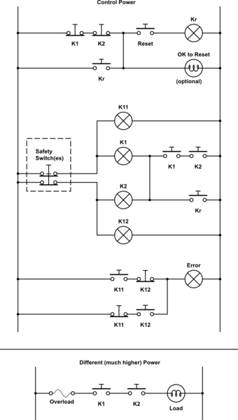
Per a comment, here's one possible version of option #2:

schematic

simulate this circuit – Schematic created using CircuitLab

Or, if you have sufficiently deep pockets, you could buy a safety rated PLC and do all of this in software with even more fault-checking and detailed diagnostics.

Please note that I am in a different industry now, and so there may have been some legal changes since I left. Check the latest electric codes, OSHA regulations, etc., before trusting this (or anything else really) to an operator.

\$\endgroup\$
12
  • \$\begingroup\$ +1 This is exactly the right way to think about E-stops. Engineering. \$\endgroup\$ Commented Feb 25, 2015 at 19:45
  • \$\begingroup\$ I'd really like to see an example diagram of this. \$\endgroup\$ Commented Feb 25, 2015 at 20:23
  • 1
    \$\begingroup\$ @phonetagger: Happy now? \$\endgroup\$
    – AaronD
    Commented Feb 25, 2015 at 21:12
  • \$\begingroup\$ Very nice answer, thanks. What I had was the e-stop allowing current to go through both the coils or the primary+redundant contactors in series; I'll rewire that in parallel for the reasons you've explained. Interesting fool-proof system, too! \$\endgroup\$ Commented Feb 25, 2015 at 21:46
  • \$\begingroup\$ The big advantage of having parallel channels is to account for one of them finding power by accident and sticking on for that reason. A single channel in that situation would appear safe as far as the detection logic is concerned, even if it was looped through two contacts of every switch. \$\endgroup\$
    – AaronD
    Commented Feb 25, 2015 at 21:51
7
\$\begingroup\$

EDIT - the original question referred to relays and not contactors. It might be confusing to see the question now referring to contactors with my answer suggesting the use of a contactor!

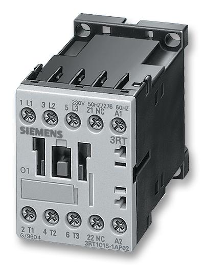
People normally use a contactor for this sort of job: -

enter image description here

Found here. Here's what wiki says about contactors and relays: -

Unlike general-purpose relays, contactors are designed to be directly connected to high-current load devices. Relays tend to be of lower capacity and are usually designed for both normally closed and normally open applications. Devices switching more than 15 amperes or in circuits rated more than a few kilowatts are usually called contactors. Apart from optional auxiliary low current contacts, contactors are almost exclusively fitted with normally open ("form A") contacts. Unlike relays, contactors are designed with features to control and suppress the arc produced when interrupting heavy motor currents.

Here is what Rockwell say about safety contactors (you may decide on this as a preferred product): -

Safety Contactors and 700S Safety Control Relays provide mechanically linked, positively-guided contacts up to 97 A which are required in feedback circuits for modern safety applications. 100S-D Safety Contactors provide safe isolation of hazardous motion loads, using mirror contact performance. Mirror contacts provide reliable indication about the open or closed status of the main power poles.

And finally, the EU machinery directive implies that hazards be assessed and appropriate safety measures taken. The impact of this is that equipment/installations can be categorized with a letter/number and appropriate equipment purchased to maintain that level of safety. I would recommend that you look into this. Here is a website related to safety relays that discusses the relevant safety categories. Incidentally you may need to use a category 3 contactor.

\$\endgroup\$
1
  • \$\begingroup\$ Thanks Andy. I was referring to high current rating relays, updated my question. My question still stands for contactors: are they virtually safe from failing closed? \$\endgroup\$ Commented Feb 25, 2015 at 16:47
4
\$\begingroup\$

Whatever the manufacturer may or may not say, I would strongly urge you to limit the consequences of such a failure by adding redundant safety features such as a thermal cutoff or mechanical stop so that injuries and intolerable property damage are prevented. Even if the relay is 100.000% reliable from that kind of failure, the driving circuitry could fail or something could jam the contactor test button or whatever.

Some products have three safety devices- one electrical, one hydraulic and one purely mechanical, because a failure could result in severe injury to an operator.

\$\endgroup\$
6
  • 1
    \$\begingroup\$ Important comment, but I don't see how that answers the question... \$\endgroup\$
    – PlasmaHH
    Commented Feb 25, 2015 at 16:35
  • 1
    \$\begingroup\$ When I was working in industrial automation, we always had two overrated contactors in series to provide a safety stop function. Neither one is likely to weld, but if one does anyway, the other is probably still good. Their coils were controlled by separate, mechanically parallel systems, which included a bit of logic around the contactors' auxiliary contacts so that it cannot be reset unless they both dropped out. (That is, if one welded or one channel of a detector failed, the system will refuse to re-energize until that's fixed.) \$\endgroup\$
    – AaronD
    Commented Feb 25, 2015 at 16:47
  • \$\begingroup\$ Good point, this is simply as a primary means of emergency stop. \$\endgroup\$ Commented Feb 25, 2015 at 16:48
  • \$\begingroup\$ Note that 99.9996% rounds to 100.000%. :) \$\endgroup\$
    – Greg d'Eon
    Commented Feb 25, 2015 at 19:04
  • 2
    \$\begingroup\$ Not when you're dealing with safety. A known point of failure can become a legal liability in a hurry, even if it's only 0.0004% likely to happen. Hence the redundancy of every shutdown function, not just multiple functions. \$\endgroup\$
    – AaronD
    Commented Feb 25, 2015 at 19:40

Your Answer

By clicking “Post Your Answer”, you agree to our terms of service and acknowledge you have read our privacy policy.

Not the answer you're looking for? Browse other questions tagged or ask your own question.