I am interested in learning more about how SPI works in general, but with the raspberry pi and py-spidev library in mind. I am very technically savvy, although not so much on the EE side of things.
I am attempting to communicate to a piece of equipment via SPI and have been given only a spreadsheet with some information regarding the byte commands and timing. I have already determined that the SPI mode is 1, clock speed should be 300kHz, and word length is 8 bits. A snapshot of the command sheet is seen below. They should be joined end-on-end.


I have attempted to communicate using the py-spidev library and have seen some hopeful numbers (I think). Example:
import spidev
spi = spidev.SpiDev()
spi.open(0, 0)
spi.mode = 1
spi.max_speed_hz = 500000

spi.xfer2([0x03, 0x00])
I am under the impression that this should turn ON the digital pot, which it does not. However, I do see the values [3, 0] returned, which leads me to believe that something is happening.
What is the difference between Bytes(s) out and Byte(s) in? I am under the assumption that if I send the command xfer2([0x03, 0x00], 500000, 9000) I should receive the bytes 0xF3 and 0x03. Is that correct?
I am really at a loss for how to proceed and would love references to good tutorials/descriptions.
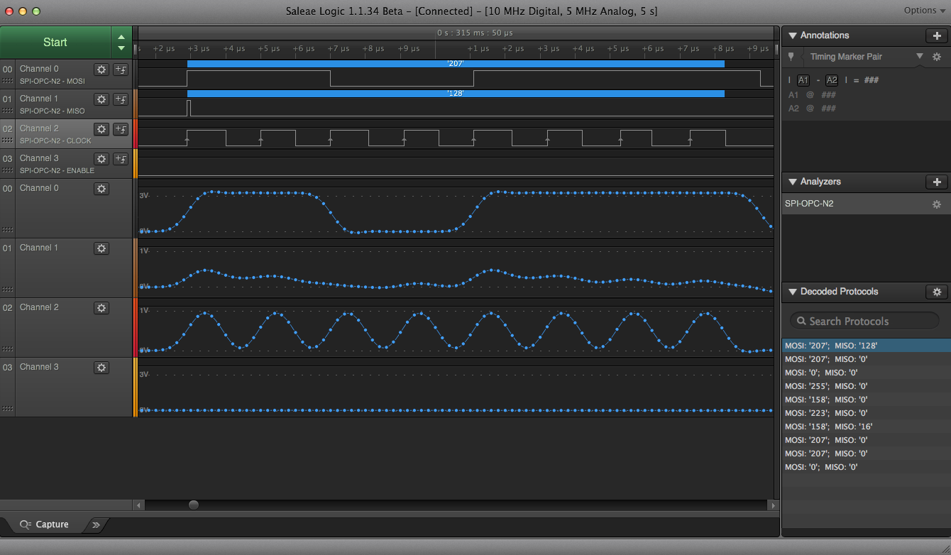
After finally receiving my Saleae Logic Analyzer, I have an update. It appears the chip select pin isn't working? Does anyone have tips for debugging this on a Pi specifically?


cshigh = True, the data that is returned is [0, 0] as opposed to [3, 0]. \$\endgroup\$