3
\$\begingroup\$

http://www.learnabout-electronics.org/Oscillators/images/astable-basic.gif

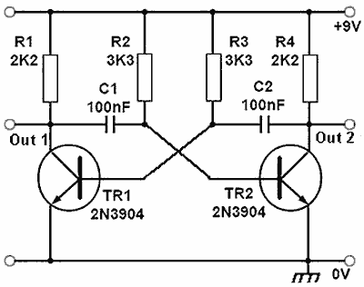
This is an astable multivibrator circuit. Assuming that TR2 is initially on, the right pin of C2 is grounded and since C2 isn't charged, the left pin of it is also at 0V. Now, Out 2 is low.

C2 is then charged up slowly through R3, until a critical moment when the left pin of C2 passes around 0.7V to activate TR1, in which the circuit flips and TR1 turns on, causing Out 1 to be low, and the cycle repeats.

However this has a problem with the rise time. Assuming that TR2 is initially on, TR1 is off and thus Out 1 will be high. However, the capacitor will cause the rising edge to be a curve and not "instant".
http://www.learnabout-electronics.org/Oscillators/images/astable-fast.gif

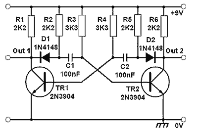
This is an improved astable multivibrator circuit, which improves the rise time by using a diode to prevent the capacitive action when TR1 is high (assuming TR2 is initially on). Instead, C1 will be charged through a separate resistor.

It works in real life, but I just can't wrap my mind around it. If D2 is there, and TR2 is on causing the right pin of D2 to be grounded, the left pin of D2 will be around 0.7V (forward voltage drop of D2). As C2 is not charged yet, the right and left pin of it will be 0.7V.

But doesn't this cause it to achieve the critical level of 0.7V already? This is where my head explodes from infinite frequency.

How does it work?

\$\endgroup\$

1 Answer 1

1
\$\begingroup\$

I can't see what the problem is here... "When TR2 is on causing the right pin of D2 to be grounded", C2 is fully charged ("-" at the left plate and "+" at the right) plate. The diode brings down its right plate and fixes it to +0.7 V. The capacitor begins to recharge and its left plate gradually increases until reaches about +0.6 V when TR1 begins turning on... and the self reinforcing positive feedback begins acting. The circuit rapidly switches... TR2 cuts off ... D2 cuts off as well... and disconnects C2 from the TR2 collector thus improving the rising edge...

So your mistake is in this assertion - "As C2 is not charged yet, the right and left pin of it will be 0.7V." C2 is charged but with the opposite polarity... and its left pin is at -8.3 V.

\$\endgroup\$
2
  • \$\begingroup\$ Sorry, I think you may have had a typo at "The diode brings down its right plate and fixes it to +7 V", in which it should read +0.7V instead. Also, I'm not quite sure how C2 charged up to 9V. I may be missing something here. \$\endgroup\$ Commented Feb 28, 2015 at 8:18
  • \$\begingroup\$ Yes, it was a typo...I have corrected it... C2 is charged up to (almost) 9V through R5 and the forward biased base-emitter junction of TR1 when TR2 is cut off. I have described it in the Operation section of the Wikipedia page about multivibrator. The clever trick used in this circuit is to charge the capacitors through the forward biased base-emitter junctions. \$\endgroup\$ Commented Feb 28, 2015 at 10:28

Your Answer

By clicking “Post Your Answer”, you agree to our terms of service and acknowledge you have read our privacy policy.

Not the answer you're looking for? Browse other questions tagged or ask your own question.