0
\$\begingroup\$

I've been trying to build a hartley oscillator and have almost succeeded, however my calculations are off by appx 1000 relative to the measured waveform. AND the kicker is that it only works when I pull out the 1u capacitor in the tank circuit. I believe that I at least have to start it with the cap in the circuit but the waveform doesn't appear on the scope until the cap is disconnected. The scope shows a waveform of 1.6mhz while I believe its supposed to oscillate at 1.6khz. Is there a separate mode of oscillation that I am seeing? Without the cap, is it just a series RLC filter in the feedback loop only allowing amplification of the series resonant frequency?

I tapped the 100u inductor at about 40/60 and have flipped it's orientation several times to try and get the gain at an acceptable level. I modeled the resistor in the tank circuit to account for inductor resistance. I wonder if the gain just isn't quite right for the intended 1.6khz oscillation, but turns out to work for the alternate series mode of oscillation. Does anyone have any insight on what's going on here?

One final point of weirdness is that upon trying to alter the series RLC feedback path by changing the emitter bypass cap to only 1u (as well as changing the other series caps) but none of this altered the waveform shown on the scope!
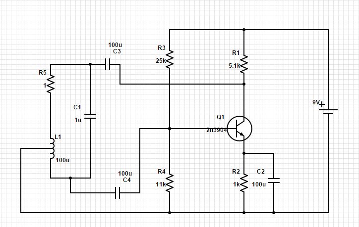
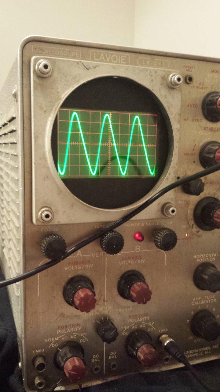
My Circuit enter image description here

\$\endgroup\$
3
  • \$\begingroup\$ Which frequency did you observe? Milli-Hertz oe MHz? \$\endgroup\$
    – LvW
    Commented Mar 2, 2015 at 16:01
  • \$\begingroup\$ My calculation for the osc. frequency gives 16 kHz (L=100u, C=1u). Try to remove C2 - then, for a BJT gain of app. 5 the inductance ratio should be app. 1/4...1/3. \$\endgroup\$
    – LvW
    Commented Mar 2, 2015 at 16:09
  • \$\begingroup\$ I observed this waveform at 1.6 MHz. It only showed up on scope when C1 was removed. Doesn't appear to be saturated though. Does this change any of your thoughts? \$\endgroup\$
    – bwjohns4
    Commented Mar 2, 2015 at 17:31

2 Answers 2

1
\$\begingroup\$

I have simulated the circuit with the following modifications:

1.) Remove C2

2.) Upper part of L1 with 30µH and lower part with 70µH.

As expected, the circuit oscillates at app. 16 kHz. I suppose, the gain (with C2) is too large - driving the BJT into severe saturation. As a consequence, undesired effects (storage times etc.) have an influence and inhibit correct operation. It should be your goal to fulfill the Barkhausen condition for oscillation with a loop gain (transistor gain multiplied by the inductance ratio) which is only slightly larger than unity.

EDIT: I have to correct my self - sorry. For my first simulation I have used an idealized transistor model - now, with a real model I couldn`t achieve self-sustained oscillations. Perhaps the loading of the resonant circuit is to heavy?

\$\endgroup\$
2
  • \$\begingroup\$ How do I go about calculating the feedback gain of this circuit? Does the inductor resistance have any effect on the closed loop gain? I think I know how to calculate small signal gain at signal frequency, but I'm confused how the tank circuit plays into that. \$\endgroup\$
    – bwjohns4
    Commented Mar 2, 2015 at 17:32
  • \$\begingroup\$ I modeled it in LTSpice and it did work, but it only produced like .2mV pp. It gives me trouble when I add resistance in the tank circuit, but with 1ohm it would still work in simulation. But in the real world it acts much differently. \$\endgroup\$
    – bwjohns4
    Commented Mar 2, 2015 at 18:23
0
\$\begingroup\$

I have finally answered my own question after a good bit of agony. I left out the part that I took a 100u inductor, unwound appx half of it, then rewound it appropriately to get the muctually coupled split inductor. It then acts like an autotransformer, doing exactly what it's supposed to, and transforms the voltage and current. The current flowing to the transistor base through the capacitors cancels out the some of the flux in the core, effectively reducing the overall inductance of the inductor used in the tank. Therefore, with a large capacitor in series with a low inductance, there is little voltage applied across the inductor and therefore across the capacitor. The circuit later worked with a much smaller (10n) capacitor but gave a higher frequency than expected due to the lower effective inductance due to the cancelling effect of the base current flowing in the lower part of the split inductor.

It only worked when the capacitor was removed because the larger capacitance forced the voltage across the base inductor to be very low. When the cap was removed, some other frequencies were favored by the LRC feedback circuit giving a very unpredictable frequency response.

\$\endgroup\$

Your Answer

By clicking “Post Your Answer”, you agree to our terms of service and acknowledge you have read our privacy policy.

Not the answer you're looking for? Browse other questions tagged or ask your own question.