1
\$\begingroup\$

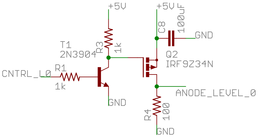
Shown in the schematic below is a typical MOSFET driven by a BJT. I know the purpose of almost everything here, except for R4. I just can't figure out what the resistor on the MOSFET's drain is for Is it some sort of pull-down? And why might it be needed here?
schematic image

\$\endgroup\$
4
  • \$\begingroup\$ What is the point of C8 to ground? \$\endgroup\$
    – sherrellbc
    Commented Mar 14, 2015 at 5:14
  • \$\begingroup\$ @sherrellbc: It's a reservoir cap used to provide a lo-Z voltage source for the load when Q2 first switches ON. \$\endgroup\$
    – EM Fields
    Commented Mar 14, 2015 at 5:29
  • 1
    \$\begingroup\$ For the love of FSM, please use the freaking ground symbol for ground connections, and the power symbol for power connections. They exist for a reason, and you're horribly abusing net-labels instead, for no good reason. \$\endgroup\$ Commented Mar 14, 2015 at 6:07
  • \$\begingroup\$ @ConnorWolf It's not my schematic, someone else made it. \$\endgroup\$
    – Techjar
    Commented Mar 14, 2015 at 7:40

2 Answers 2

9
\$\begingroup\$

Given that you have said that the output line goes to an array of LEDs, I think that R4 is there to quickly discharge the LED capacitance when the FET is turned OFF. This would minimize ghosting if the LED array is multiplexed quickly.

I used to run into that problem with some of the large LED arrays we used to build many years ago. Adding a low-value resistor to quickly discharge the charge stored in the LEDs reduced or eliminated the ghosting problem.

\$\endgroup\$
2
  • 1
    \$\begingroup\$ Bingo! +1 for you. \$\endgroup\$
    – EM Fields
    Commented Mar 14, 2015 at 6:20
  • \$\begingroup\$ I didn't even think about the stray capacitance, that actually makes a lot of sense. The LEDs are actually being multiplexed at a quite high frequency. \$\endgroup\$
    – Techjar
    Commented Mar 14, 2015 at 7:43
0
\$\begingroup\$

Q2 is a P-channel MOSFET, so yes, R4 is a pulldown and part of the load Q2 is working against.

\$\endgroup\$
5
  • \$\begingroup\$ What is the drain pull-down necessary for though? Fast switching or something of that sort? \$\endgroup\$
    – Techjar
    Commented Mar 14, 2015 at 5:05
  • \$\begingroup\$ It serves the same purpose as does R3, which is to provide a voltage drop when charge flows through it. \$\endgroup\$
    – EM Fields
    Commented Mar 14, 2015 at 5:17
  • \$\begingroup\$ It seems to me like R4 is used to limit the on-state current through the MOSFET, as well as provide the node where the voltage is measured. \$\endgroup\$
    – sherrellbc
    Commented Mar 14, 2015 at 5:17
  • \$\begingroup\$ @sherrellbc: With an Id rated at -17 amperes, I doubt it. \$\endgroup\$
    – EM Fields
    Commented Mar 14, 2015 at 5:34
  • \$\begingroup\$ The line labeled ANODE_LEVEL_0 goes to a large array of LEDs, so R4 isn't for current limiting. \$\endgroup\$
    – Techjar
    Commented Mar 14, 2015 at 5:40

Your Answer

By clicking “Post Your Answer”, you agree to our terms of service and acknowledge you have read our privacy policy.

Not the answer you're looking for? Browse other questions tagged or ask your own question.