1
\$\begingroup\$

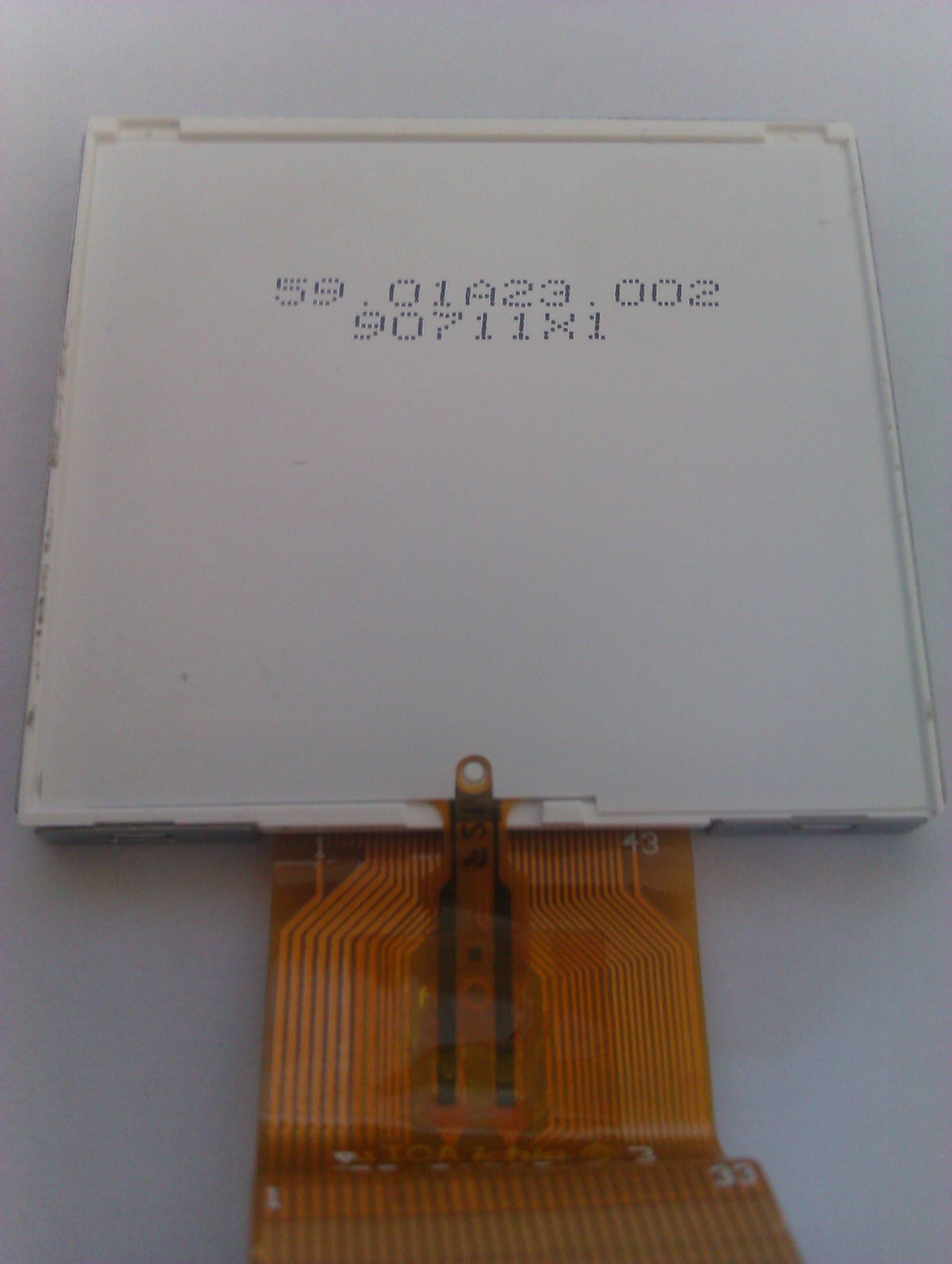
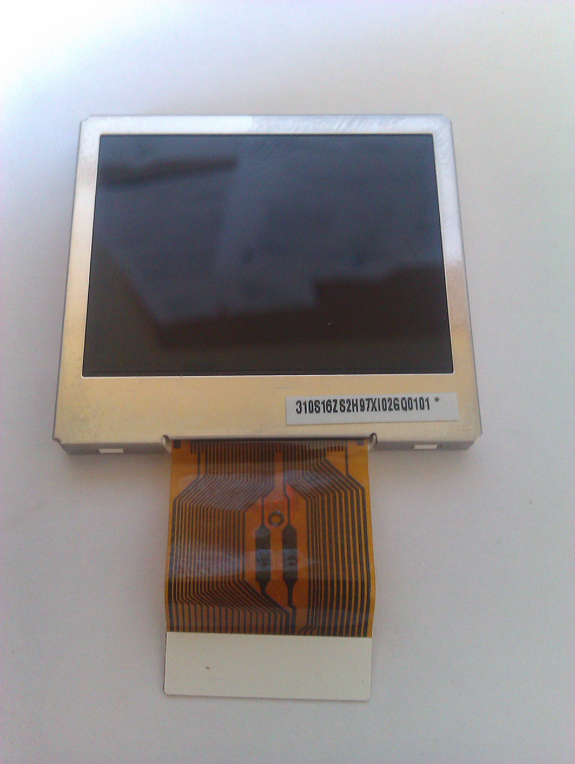
Right, so I have ripped the 1.7" (ish) TFT module out of an HP PhotoSmart C4780. Despite HP's best efforts I can plainly see that it is made by AUO. No model number on it though.

Now, I have never had anything to do with TFT screens before now, but I want to have a play.

The screen has a single mylar strip connector, and I can see which of the connections break off to the back-light, so that's not a problem.

From what I can see the rest of it doesn't need anything 'special' - the board it normally plugs into is powered by a PIC16F727, so it must be possible for me to interface it to some other PIC instead (I have a selection to hand).

But how do I get started? I don't even know what connections to expect there to be on the mylar strip, and how to work out what should be where.

I have found some AUO data sheets, but none for a 1.7", only 1.5" and 2" and upwards, though I have identified one possible 1.7" model - A017CN01, but I can't find a data sheet for it anywhere.

Any pointers would be most appreciated.
enter image description here enter image description here

****Update:****

I think I may have just found a data sheet for this device - I'm still none the wiser though...

I see it has a serial data (SPI-like) interface to it - ideal for PIC usage. Nothing in the data sheet about how to use it. Would this interface be likely to be common to all AUO devices?

\$\endgroup\$
7
  • 2
    \$\begingroup\$ My usual recommendation: if you can't find a datasheet, ditch it. Datasheets are so essential in design, and picking up information left and right won't tell you everything you need. \$\endgroup\$
    – stevenvh
    Commented Jun 26, 2011 at 11:27
  • \$\begingroup\$ @stevenvh yeah, I agree, but if I could just confirm a part number I might have a chance of getting a data sheet \$\endgroup\$
    – Majenko
    Commented Jun 26, 2011 at 11:28
  • \$\begingroup\$ I think I may have found a data sheet - yslcd.com.tw/docs/product/A017CN01%20V.4.pdf - but still no clue ;) I see it has a serial interface - any idea how to use it? \$\endgroup\$
    – Majenko
    Commented Jun 26, 2011 at 11:39
  • \$\begingroup\$ Interface is parallel; look at the bottom of the table on page 6. BTW, why don't you add the link to your question? \$\endgroup\$
    – stevenvh
    Commented Jun 26, 2011 at 11:45
  • \$\begingroup\$ @stevenvh I already did ;) \$\endgroup\$
    – Majenko
    Commented Jun 26, 2011 at 11:46

2 Answers 2

3
\$\begingroup\$

You may (or not) may have found a datasheet. Unless you can find back the ID numbers on the actual device there's no way to tell with absolute certainty. Checking dimensional properties is the first job. If dimensions differ, it may be at best a variant, but also there: no certainty.
If you're confident enough that you have the right datasheet, scrutinize it. This may not be a pleasant task, especially when a datasheet has several hundreds of pages, but here the most interesting parts are easy to spot: the timing diagrams on pages 14 and 15 reveal a lot. Like the VSYNC and HSYNC. They tell you that this isn't a device with its own intelligence and memory, but rather that you have to drive it like a video signal, doing the refreshing yourself.
OTOH, like you said there are also the SDA and SCL connections, which hint at I2C, though the (again) timing diagram page 29 shows that it's more SPI-like (It lacks the I2C starting sequence). The pages following show that the serial interface isn't used for image data, but to program configuration registers.

\$\endgroup\$
1
  • \$\begingroup\$ The page numbers @stevenh gives are the page numbers in Acrobat Reader. The page numbers in the page headers of the document are 1 page off. \$\endgroup\$ Commented Jun 26, 2011 at 12:50
3
\$\begingroup\$

Video data is fed into the screen by drawing with a cursor based on HSYNC and VSYNC signals. These indicate the next row and next column. A 8-bit databus indicates the color data. Because this is 8-bits and colours are usually 16-bit or 24-bit, it means you need to have 2 or 3 periods of DCLK (data color clock) to draw 1 pixel. The datasheet even talks abuot having a dummy value to clear the pixel.

A PIC16F is incapable of doing this. The DCLK needs to be between 16 and 27MHz. At DCLK @ 23040kHz (23.04MHz) you can get a refresh rate of 50Hz, which is kinda a minimum for display quality. HSYNC and VSYNC are dependant on how the screen is drawn; top-bottom or left-right. It may be that HSYNC is 23.04MHz/4=5.76MHz and VSYNC is 23.04MHz/4/480=12kHz.

In other words, the PIC16F probably connects to some kind of internal bus (may be a UART or something else) so a main controller can easily speak to it. The PIC16F is probably used to configure contrast, backlight values etc.

\$\endgroup\$
4
  • \$\begingroup\$ UPS501 mode runs at 9Mhz or so, which might be doable with a PIC \$\endgroup\$ Commented Jun 28, 2011 at 4:35
  • \$\begingroup\$ A PIC 16F running at 16MHz have a computation rate of 4MIPS. 4 clocks ticks per command. \$\endgroup\$
    – Hans
    Commented Jun 28, 2011 at 18:17
  • \$\begingroup\$ only if you keep the frame rate at 50Hz. \$\endgroup\$ Commented Jun 28, 2011 at 22:52
  • \$\begingroup\$ Another major problem when attempting to drive a VGA display with a small PIC/AVR is the small amount of workable memory - you don't have enough RAM to store all the pixels and you do not have time to compute anything on the run (i.e. in order to store screen data in vector form). Here is a many page simple explanation how to make a simple video card with atmega644 :) \$\endgroup\$
    – Vorac
    Commented Nov 27, 2012 at 15:57

Your Answer

By clicking “Post Your Answer”, you agree to our terms of service and acknowledge you have read our privacy policy.

Not the answer you're looking for? Browse other questions tagged or ask your own question.