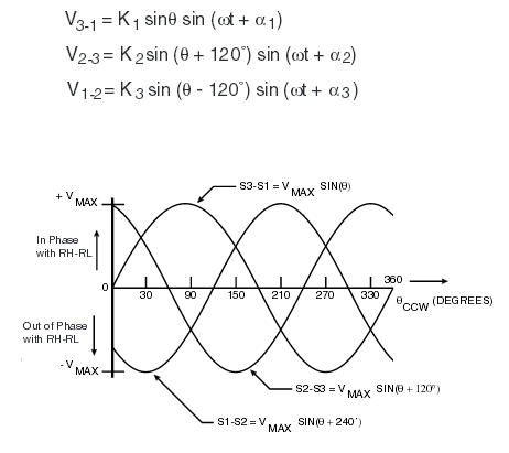
I'm trying to understand how to get the value of the shaft position from a synchro. I've looking in mutiple documentation but none explains how to calcuate the angle value from :

I'm looking to get Theta
I'll be thankful for any hint
I'm trying to understand how to get the value of the shaft position from a synchro. I've looking in mutiple documentation but none explains how to calcuate the angle value from :

I'm looking to get Theta
I'll be thankful for any hint
There are several approaches, but all of them are based on converting the 3-phase signal to a 2-phase signal, with the amplitudes of the two signals proportional to the sine and cosine of the shaft angle. With the two amplitudes detected, the angle can be computed via the arctan function (paying due attention to polarities to get the quadrant right).
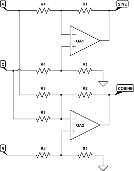
The transformation was originally performed using a Scott-T transformer (this was back in the days of vacuum tubes), but a pair of op amps will do the trick. See http://www.analog.com/media/en/technical-documentation/application-notes/50205505838923AN252.pdf for a detailed discussion, along with resistor values.
Briefly, the circuit looks like

simulate this circuit – Schematic created using CircuitLab
And the resistors are scaled to produce
SINE = C - A
COSINE = (2/sqrt 3)(B - A/2 - C/2)
Since different synchros use different voltages, you have to pick the appropriate scale factors suitable to your specific device.
Here is an equation for using the ATAN2 function for calculating the synchro shaft angle "THETA" from the amplitudes of the two synchro signals S1 and S2.
THETA = DEGREES(ATAN2((S2/S1 + 0.5), 0.866))
The derivation is explained below:
Analysis uses the standard definitions of the synchro signals S1 and S2, and some mathematical derivation. These are the standard definitions of synchro signals:
S1 = K * SIN(THETA)

S2 = K * SIN(THETA + 120 degrees)

S3 = K * SIN(THETA + 240 degrees)
K is the amplitude of the voltages, and THETA is the synchro shaft angle being driven inside the indicator (and perhaps reduction geared to the indicator needle). Since S3 is only used to provide extra mechanical force in complex indicators, we do not use it in analysis and S/D data conversion. Since K is different for each sensor and indicator, and can be slightly different from aircraft to aircraft or even in a single aircraft under different operating conditions, we eliminate it from the analysis by dividing, using the simplicity of the S1 definition as the term in the denominator:
S2/S1 = K * SIN(THETA + 120 degrees) / K * SIN(THETA)
The K’s cancel out…
And, using the trigonometric identity for the Sine of the sum of two angles, we derive:
SIN(THETA + 120 degrees) = SIN(THETA) * COS(120 degrees) + COS(THETA) * SIN(120 degrees)
Note that this relationship is true for every synchro signal, regardless of reference voltage, frequency, signal loss, etc.
COS(120 degrees) = -0.5

SIN(120 degrees) = 0.866 (square root of 3 divided by 2)
Now we have this relationship for S1 and S2:
S2/S1 = -0.5 * SIN(THETA) / SIN(THETA) + 0.866 * COS(THETA) / SIN(THETA)
This simplifies to:
S2/S1 = -0.5 + 0.866 * COT(THETA)

COT(THETA) = (S2/S1 + 0.5) / 0.866
There are not any readily available computer functions for calculating the arc-cotangent, but there are excellent functions for calculating arc-tangent, so we invert the relationship:
TAN(THETA) = 0.866 / (S2/S1 + 0.5)
Note: software SMEs will see that once we have a relationship for Cotangent, simple substitution of variables can be used for the arc-tangent function. I’m being complete here for the sake of, well, completeness. :)
The ATAN2 function is designed to handle the inevitable divide-by-zero cases that can occur with fractions.
So, the coding is:
THETA = DEGREES(ATAN2((S2/S1 + 0.5), 0.866))
How cool is that!? With just two voltage measurements – S1 and S2 – we easily get the synchro angle THETA. And this works for any synchro system…
S2/S1 is a fraction, with S1 in the denominator, so the code has to protect against the case where S1 is equal to zero (or very close to zero). The synchro angle THETA crosses a quadrant somewhere in its range, typically at 180 degrees, so we have to look at the THETA angle to find the sudden change in sign and/or magnitude, and then do a simple addition or subtraction of 180 degrees. These typically occur when S1 is less than zero.
The end result is a synchro angle THETA that is a straight line when plotted against the original indicator values. The simple relationship Y = mX + b is used to convert the synchro angle THETA into the displayed units of the analog mechanical indicator, now ready for a digital display as symbology and/or readout.
θ, Ω, μ, ° which are rather useful for electrical engineering directly in your posts (but they don't render in the comments).
\$\endgroup\$
Commented
Jun 2, 2019 at 21:01