0
\$\begingroup\$

I'm using a PNP MOSFET to replace a physical button. When I ground the lead I've attached to bypass the switch, the action I need activates (a notification light comes on - it's the activator button on this barcode scanner), so I know I'm working with the right lead.

In the same test, when I insert a DMM into the loop, I see that when pressed, there's about 60uA going through it.

My circuit is as follows:
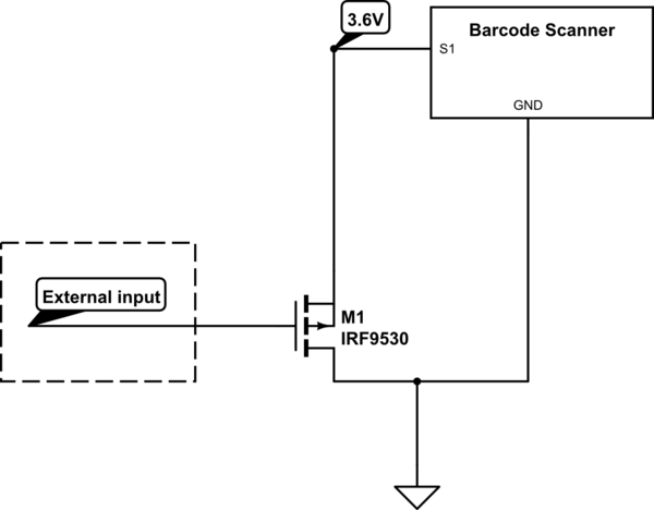
schematic

simulate this circuit – Schematic created using CircuitLab

The gate voltage goes from 5V to 0V when expected, and when I put a DMM between the drain of the MOSFET and ground, I can see ~55uA when the MOSFET is activated. However - the indicator light doesn't turn on.

Any ideas of what I should look for?

The external input is the circuit described in this question, but with a P channel instead of an N channel, as my sensor output goes high when it needs to be off, and low otherwise.

Here's the mosfet I'm using: http://www.diodes.com/datasheets/ZVP4424A.pdf

\$\endgroup\$
5
  • \$\begingroup\$ well, you've got a ridiculously high resistance "on" MOSFET, with crazy over-the-top 200V rating. But hey, at least it will turn on with only 1.4-2V Vgs. Have you got a resistor pulling up the gate of the FET? If the "external input" goes low, it will turn on the PFET. If the external input goes high, it will turn the PFET off, as long as it's going higher than or equal to 3.6V \$\endgroup\$
    – KyranF
    Commented Mar 28, 2015 at 5:20
  • \$\begingroup\$ also, 55 microamps is probably just the leakage current. \$\endgroup\$
    – KyranF
    Commented Mar 28, 2015 at 5:21
  • \$\begingroup\$ @KyranF I grabbed the cheapest / first part I could that had the right Vgs. Not a high-frequency thing, so I don't really care about the rest of the parameters (right?). The scenario you describe is what I'm looking for. \$\endgroup\$
    – kolosy
    Commented Mar 30, 2015 at 2:40
  • \$\begingroup\$ See additions to my answer. | What happens if yu just drive S1 from the input line? | What is the input voltage swing? | It is a very good idea to present all relevant data such as voltage levels etc in the question as referring to prior questions is OK for background within reason but hard if it is needed to get basic circuit conditions. We need to know vin voltage swing and current capability anmd ... \$\endgroup\$
    – Russell McMahon
    Commented Mar 30, 2015 at 15:42
  • \$\begingroup\$ Then put a 10k resistor from the gate of the PFET to the 3.6V line, and when the "external input" pulls the gate down to 0V, the PFET will turn on. When the external input lets go/drives high, the resistor will make sure it turns off the PFET. \$\endgroup\$
    – KyranF
    Commented Mar 30, 2015 at 16:03

1 Answer 1

0
\$\begingroup\$

Measure the MOSFET source (connected to scanner) when the MOSFET is ON.
You'll find it does not pull down to ground as the MOSFET needs a voltage of about Vgsth to just start to turn on. You are probably getting 1+ Volts source to ground. source-

Driving an NChannel MOSFET , source to ground, drain to scanner should work. The drive sense will be inverted. This can be fixed if needs be.

If you wish to use the P Channel FET try a 100k scanner in to ground to see if it turns on. If not try lower R till it works. Then pull scanner input UP with MOSFET, source to V+, drain to scanner in. Again, polarity reversed.


Magic :-):

This circuit converts

  • A High / Ground signal at the MOSFET source

into

  • An open_circuit / ground output at the MOSFET drain..

The external input voltage swing and current sinking ability has not been specified.
The circuit below will convert a 0 to V1 signal to 0 to V2 where V2 > V1, OR to a 0 /Open circuit output.

In this case when Vin is high, when (Vdd-Vin) < Vgsth_FET the FET will be off.
When Vin = 0, if Vgsth_FET < Vdd then FET will be on.
The input line needs to be able to sink the current from S1 - which is said to be low show it should work.

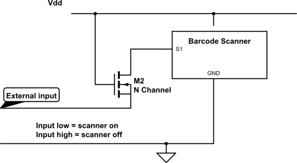
N Channel FET.
Switching polarity as original. Input low = on. Gate to V+, drain to scanner, source to external input.

schematic

simulate this circuit – Schematic created using CircuitLab

\$\endgroup\$
5
  • \$\begingroup\$ So - switching to an n-channel works, but as you note, inverts the logic. I'm not entirely sure I follow the magic of getting the p-channel working. You're right, Vsource goes from 3.6 to 1.45 when Vgate goes low. I found a resistor which doesn't prevent the switch from working (22k), but I don't entirely follow the wiring you suggest. I have S1 pulled up with 22K res, going into source, drain to ground. The switch works by driving S1 to ground, so I'm not sure what you're suggesting. \$\endgroup\$
    – kolosy
    Commented Mar 30, 2015 at 2:38
  • \$\begingroup\$ @kolosy I just took my text above and drew 3 diagrams doing EXACTLY and ONLY what I had written above. Each of the diagrams I ended up with was what I was intending to convey. If you draw diagrams using exactly what I have written above you should get the same result. Try them. | You do not need to understand the magic of the N channel source-input solution (not P Channel as you say) initially - magic is like that. Try it . If it works for you (it should) then try to work it out and if that fails then ask . \$\endgroup\$
    – Russell McMahon
    Commented Mar 30, 2015 at 5:05
  • \$\begingroup\$ As I said, I tried the N-Channel, and it worked, but the logic is inverted. That's why I went down the P-Channel path to begin with - I need the switch to be off when my input is high, and I don't follow what you're saying re: the "pull the scanner up with mosfet" etc. \$\endgroup\$
    – kolosy
    Commented Mar 30, 2015 at 13:37
  • \$\begingroup\$ This works. To make sure I understand what's happening - the n-mosfet doesn't conduct when external input is high because there's no differential between gate and source; then, when input goes low, the gate is already tied high, and it starts conducting, right? \$\endgroup\$
    – kolosy
    Commented Mar 31, 2015 at 1:47
  • \$\begingroup\$ @kolosy - By "This works" do you mean that the N channel circuit with driven source actually worked for you in the real world? If so, good. | Yes - your description is correct. |Now try this :-): total components = 1 x Schottky diode. Connect diode wit cathode to input and anode to S1. Does it work? If so, try a silicon diode. Report back. \$\endgroup\$
    – Russell McMahon
    Commented Mar 31, 2015 at 4:36

Your Answer

By clicking “Post Your Answer”, you agree to our terms of service and acknowledge you have read our privacy policy.

Not the answer you're looking for? Browse other questions tagged or ask your own question.