5
\$\begingroup\$

I'm extremely new to circuits and am having some trouble with a variation on the voltage divider problems I've been doing.

I'm trying to determine \$V_{out}\$ in the following circuit relative to some \$V_{GND}\$ that I need to determine the location of
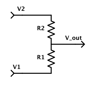
F1 .

I know that in a standard voltage divider, the line to \$V_{out}\$ carries negligible current. In this case, I can't quite determine the current flow because the lines from \$V_2\$ and \$V_1\$ carry current that is equal to \$V_2/R_2\$ and \$V_1/R_1\$ at the point in between the two resistors. How does this return to ground, and how would I begin to apply Kirchoff's Law for the loop?
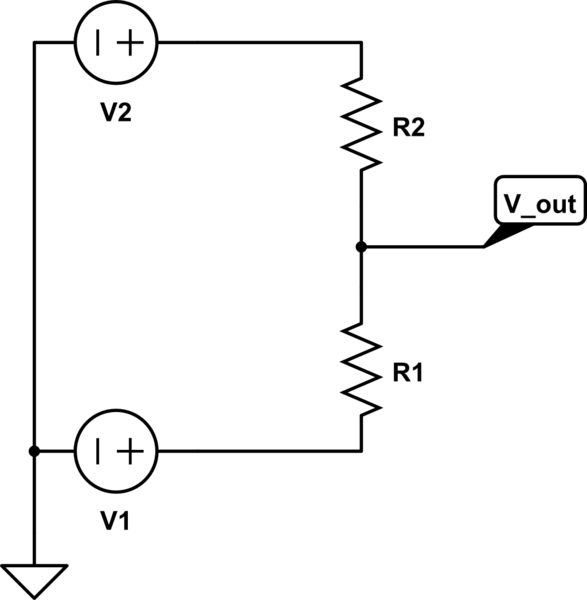
schematic

simulate this circuit – Schematic created using CircuitLab

I would think that ground node positions would be like this, but I'm nevertheless confused about the current flow. Any advice would be appreciated.

\$\endgroup\$
3
  • \$\begingroup\$ Why is your vout connected to the ground? \$\endgroup\$ Commented Apr 6, 2015 at 1:27
  • 1
    \$\begingroup\$ Right, that wouldn't make sense. So V_out goes to some voltmeter that is connected to ground, but not to ground itself? \$\endgroup\$
    – Henry H.
    Commented Apr 6, 2015 at 1:39
  • \$\begingroup\$ yes! It means you're taking the voltage at that node with respect to the ground. \$\endgroup\$ Commented Apr 6, 2015 at 2:04

2 Answers 2

5
\$\begingroup\$

I can't quite determine the current flow because the lines from \$V_2\$ and \$V_1\$ carry current that is equal to \$V_2/R_2\$ and \$V_1/R_1\$ at the point in between the two resistors. How does this return to ground, and how would I begin to apply Kirchoff's Law for the loop?

Hmm. I don't agree with this. I think you came up with these equations with the old schematic, which had an extra ground connection.

The actual current through the resistors is $$ I_1 = \frac{V_1 - V_{out}}{R_1} $$ and $$ I_2 = \frac{V_{out} - V_2}{R_2} $$ Since there is no path for current to take another loop, these currents must be the same! That means that $$ \frac{V_1 - V_{out}}{R_1} = \frac{V_{out} - V_2}{R_2} $$ and some math gives you $$ V_{out} = \frac{V_1 R_2 + V_2 R_1}{R_1 + R_2} = \frac{V_1 R_2 + V_1 R_1 - V_1 R_1 + V_2 R_1}{R_1 + R_2} = V_1 + (V_2 - V_1)\frac{R_1}{R_1 + R_2} $$ Notice that if \$V_1 = 0\$, you get back the equation that you're used to: $$ V_{out}|_{V_1 = 0} = V_2\frac{R_1}{R_1 + R_2} $$

\$\endgroup\$
3
  • \$\begingroup\$ That makes perfect sense! I'll try to do the calculation again myself, keeping this in mind. Thank you! \$\endgroup\$
    – Henry H.
    Commented Apr 6, 2015 at 2:29
  • \$\begingroup\$ Awesome. Hit those upvote/accept buttons if it works out :) \$\endgroup\$
    – Greg d'Eon
    Commented Apr 6, 2015 at 2:31
  • \$\begingroup\$ Any chance you can clarify that "some math"? Im trying to replicate it but i get stuck, mine looks like $$V_{out}=V_2\frac{R_1}{R_1+R_2}+\frac{V_2}{1-\frac{R_2}{R_1}}$$ \$\endgroup\$ Commented Apr 15, 2021 at 1:29
1
\$\begingroup\$

It's still the same voltage divider. The only difference is that now your Vin is (V2-V1) and your Vout is with respect to V1. So Vout = (V2-V1)*R1/(R1+R2)+V1.

\$\endgroup\$

Your Answer

By clicking “Post Your Answer”, you agree to our terms of service and acknowledge you have read our privacy policy.

Not the answer you're looking for? Browse other questions tagged or ask your own question.