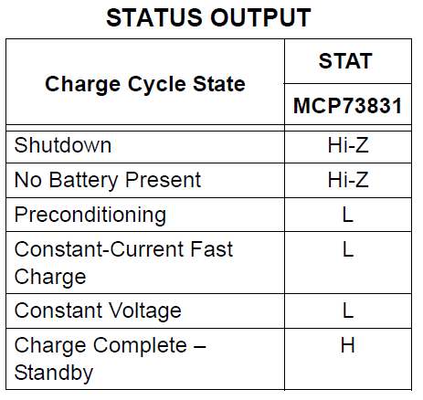
I have been building a Li-Ion charge controller with MCP73831. The STAT pin has 3 states as shown below:

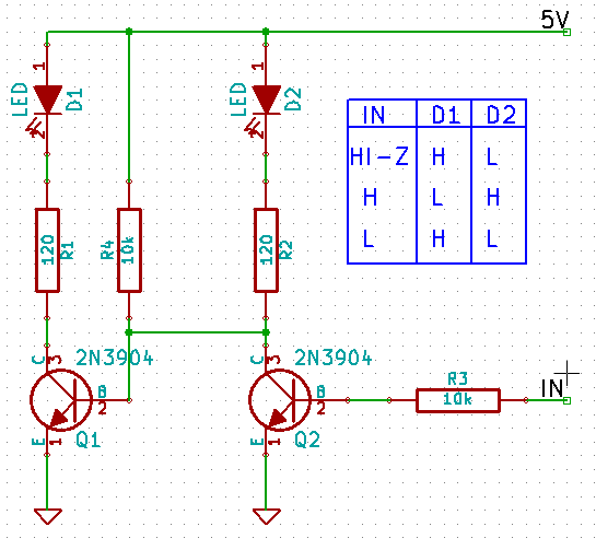
The circuit I come up so far is this:

Is there a way to detect the HI-Z state with another transistor and an LED?
I have been building a Li-Ion charge controller with MCP73831. The STAT pin has 3 states as shown below:

The circuit I come up so far is this:

Is there a way to detect the HI-Z state with another transistor and an LED?
The best way to measure the Hi-Z state is to hook up a voltage divider to the output. When the output is not being driven, the voltage will settle at the potential set by the voltage divider, which provides you with a third voltage to measure.
Distinguishing these three voltages using transistors is tricky, and probably not worth it - using an MCU, or failing that, window comparators, is a better solution.
I'm reasonably new to circuit design, but was struck with the same problem in that I did not want to put 5v on my 3.3v MCU. I also wanted something that did not draw much current.
As an alternative to the voltage divider that others have suggested, I used a second GPIO pin of the MCU to toggle a pull-up / pulldown resistor using a P-Channel and N-channel MOSFET (see circuit below). I then took STAT and put it through a simple inverted to ensure it is within the MCU 0v - 3.3v range. Note: Weaker Pull-up and pulldown resistors could probably be used to even further reduce current usage.
For this to work, the MCU would then need to take 2 readings, the first with CTL low and the second with CTL high. If the readings change, then ~STAT must be floating.
Hope this helps everyone.
I don't think so. You cannot know the potential of your hi-Z output, as it is is tied to no potential.
If you look at page 2 in the datasheet, you see that the output pin is driven by two mos-fets that are leading to the high impedance output. The voltage at 'IN' will be anywhere between Vdd and Vss. Thus, there might be a different voltage, every time the Output is switched to hi-z.
Use R and 2R resistors. R can be 1.8k, then 2R is 3.6k. Wiring: VCC--[2R]--A--[R]--SIGNAL--[R]--B--[2R]--GND
(A XOR B) = /(SIGNAL=="Hi-Z")
If SIGNAL==Hi-Z, A is 2/3VCC (logical HI), B is 1/3VCC (logical LO). Please continue...
You could try the following configuration. It shows one LED for high, the other LED for low and both LEDs (slightly dimmer) for Hi-Z.
Check that your input voltage is enough to turn both LEDs on in series. You could also consider making the resistor a higher value if you have particularly bright LEDs, to avoid dissipation in the charger IC.