5
\$\begingroup\$

Conjecture

If it's the case that

$$ Cg = {Qg \over Vg} $$

It must be the case that

$$ (Ciss + Coss + Crss)Vg = Qgon $$

But it turns out that it is not. I don't understand what I'm missing.

I know it's something to do with the fact that the actual capacitance a driver charges is not going to be including the \$ Crss \$ and maybe even not include the \$ Coss \$, but that just makes me even more wrong in the equation, so...

enter image description here


Reasoning

http://ixdev.ixys.com/DataSheet/99175.pdf

I wanted to calculate the capacitance of the gate with the charge and test voltage so I could check the time it took to turn on and off.

So then I did the following to see if I was doing it right;

  • Ciss = 8000pF = 8nF
  • Coss = 1300pF = 1.3nF
  • Crss = 220pF = 0.22nF

  • Qgon = 185nC

  • Vg = 10V

$$ (Ciss + Coss + Crss)Vg = Qgon $$

$$ (9.52nF)10V = Qgon $$

$$ 95.2nC \neq Qgon $$

What did I miss exactly?

I mean if you just do it to the 185nC you end up with 18.5nF, obviously, but there's no value on the datasheet that indicates that you'd actually be driving that value besides from the 185nC, which apparently you cannot calculate based off of the other values on the sheet. Shouldn't you be able to determine the capacitance you must be charging by taking a look at the input and output capacitances minus the leakage?

I'm so confused right now.

\$\endgroup\$

2 Answers 2

3
\$\begingroup\$

You're being confounded by Cgd (same as Crss). Two main points:

  • Cgd is very dependent on Vds.
  • Cgd gets swept through Vds-peak + Vgs-peak. Not just Vgs.

First, look at Figure 11 and Cdg. Note that at Vds = 25V, Cgd is the tabulated 220pF. But what is it at 5V ... 700pF. And what is it at 1V ... ~8000pF. 18nF not looking so unreasonable now.

So, to get the 185nC number in the datasheet, as shown in Figure 10, you would have to integrate Cdg from 125V to 0V + Vgs-peak, and then add the Cgs contribution.

Also relevant, 66660 and 74867.

\$\endgroup\$
2
  • \$\begingroup\$ Ohhh... I see it now. Wait so you're saying that the more voltage you feed your H-bridge, the easier it is to drive the gates, right? Cause as Vds goes up, the Cgd goes down, therefore the Qgd must be going up? \$\endgroup\$
    – ARMATAV
    Commented Apr 20, 2015 at 22:17
  • \$\begingroup\$ @ARMATAV Not exactly, switching loss goes up as Vds increases, just not as much as it would if Cgd were constant. That Cgd is a function of Vds is why gate charge is used for switching calculations. Using gate capacitance directly is too complicated. \$\endgroup\$
    – user16497
    Commented Apr 21, 2015 at 3:24
1
\$\begingroup\$

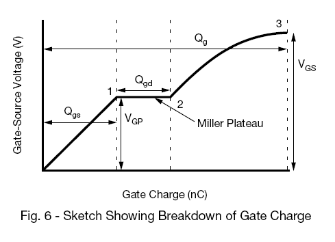
You're missing that the gate charge is specified at Vd = 0.5Vdss = 125V. The charge on Crss must also be supplied through the gate. I suggest reading this Vishay application note:

Power MOSFET Basics: Understanding Gate Charge and Using it to Assess Switching Performance.

The below diagram is taken from there.

In this case:

Qg = 185nC

Qgd = 80nC

Qgs = 50nC

enter image description here

\$\endgroup\$

Your Answer

By clicking “Post Your Answer”, you agree to our terms of service and acknowledge you have read our privacy policy.

Not the answer you're looking for? Browse other questions tagged or ask your own question.