2
\$\begingroup\$

I'm very new to electronic projects, I know the BASICS of circuits (i.e Ohms law, capacitance)but I've never constructed something on my own.

For my project I want to take the side fan for my computer case, which is a 4-pin connection to the power supply, and which also powers an LED on the fan, and interface it with a micro-controller to change fan speed based on temperature and and also user input, so it has the fan speed increases from the user pressing a button or from automatic temperature readings and a strip of LED's to light up in a row, like a progress bar to show fan speed "intensity".

With my basic knowledge I've come up with some questions that I THINK would need to be answered to do this project. As far as I know, fan speeds can be manipulated by a changing voltage, so I'm ASSUMING that I need to build a circuit of resistors that can change this output voltage value based on switches that are turned on by the micro controller, is this correct? And I'm trying to find a way that I can interface the 4-pin connection with my micro-controller? Also what kind of battery or powersupply do I need to power this circuit? Do I need to know the wattage needed for the fan? Thanks to anyone who lends me advice, It's much appreciated.

Here is the board specifications if needed http://www.socialledge.com/sjsu/index.php?title=SJ_One_Board

And a link to the fan being used. http://azzatek.com/PDF/CSAZ-1000-Solano-Users-manual.pdf (fan on the side)

\$\endgroup\$
1
  • 1
    \$\begingroup\$ Let me try to get you organized a bit. What you need to know is that fans in these applications are rarely controlled by voltage. Depending on the exact type they may not change rpm with supply voltage at all. So how are they controlled I hear you ask. Search the Internet for "4 Pin Fan Connector Pinout" and you'll find information similar to this: allpinouts.org/index.php/Motherboard_%28CPU%29_4_Pin_Fan The last link on that page points to very useful information: formfactors.org/developer/specs/REV1_2_Public.pdf It explains PWM and how it is used to control your fan. \$\endgroup\$
    – jippie
    Commented Apr 22, 2015 at 5:31

1 Answer 1

1
\$\begingroup\$

First of all, you are over-thinking. Solution is simpler than you think.

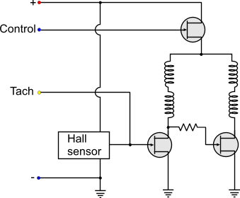
CPU fans are BLDC fans with four pin connector - VCC, GND, Tachometer output and Input. Here is a diagram:

BLDC 4 pin connection

Connect VCC and GND normally. Use Tachometer output to sense current speed of the fan. In most cases it will give you two pulses per revolution. So you can count those pulses using your microcontroller and get the fan rpm.

For speed control, you need to give a PWM signal to the control pin. Here are some links that will help you learning more about it:

http://www.arduino.cc/en/Tutorial/PWM

http://www.arduino.cc/en/Tutorial/SecretsOfArduinoPWM

So here is the solution:

1 pin for tachometer (speed) sensing - You count the pulse to display rpm.

1 pin for PWM output - You use pwm to control fan speed and monitor with speed sense pin. If current speed is less than desired speed, you increase the duty cycle till both match.

1 pin for temperature sense - you define an equation or a table describing what speed at what temperature.

UART or something else for user input/output.

You can also use LCD displays for displaying the current rpm.

Edit (added some info provided by Michael Karas in the comments below)

You might want to run the PWM waveform at micro-seconds(i.e. megahertz frequency) speeds - not milliseconds(kilohertz) speeds. Optimum PWM frequency for small fan motors is greater than 25KHz. This eliminates audible frequency noise due to the PWM. It also puts the high speed on/off of the fan to much greater than the motor drive waveforms so that the PWM truly has a chance to average the voltage in the windings instead of interacting with the BLDC drive waveforms.

\$\endgroup\$
6
  • \$\begingroup\$ Thank you so much for your explanation I will research this! \$\endgroup\$
    – Arfondol
    Commented Apr 22, 2015 at 9:50
  • \$\begingroup\$ Could you go more into depth on things for me? I have extremely basic knowledge and I've been trying to research all of this but I find it very overwhelming. The board receives temperature data from its sensor, and in the code you use the data to send output to the fan. But my board cant power the fan alone right? So it has to send a signal to a external power supply? And then after there what exactly happens, I understand PWM a little bit, but I don't understand how it could change fan speed. Does it have to do with voltage input to the fan? Do I need to make a circuit to change this? Sorry \$\endgroup\$
    – Arfondol
    Commented Apr 25, 2015 at 7:56
  • \$\begingroup\$ Fan is connected to external battery. Microcontroller's ground is connected to the ground of external battery to have a common reference point for both. Alternatively, you can power your fan and micro-controller with the same battery if possible. You send the PWM signal directly to the fan's control pin. PWM is just On Off at a high rate. It produces less effective voltage across the fan thereby reducing it's speed. \$\endgroup\$ Commented Apr 25, 2015 at 22:21
  • \$\begingroup\$ Consider the case: You have a motor and a battery of 5V. Motor's speed is 100 rpm. I ask you to drive it at 50 rpm. So you connect the motor to battery for half minute and disconnect it for another half minute and tell me - "Hey in 1 min, it rotated only 50 turns, so there you go. You have 50 rpm". PWM is same technique. Only difference is that you are switching it On and Off for milliseconds rather than half min. \$\endgroup\$ Commented Apr 25, 2015 at 22:24
  • 1
    \$\begingroup\$ @Whiskeyjack - Actually you want to suggest running the PWM waveform at usec speeds - not msec speeds. Optimum PWM frequency for small fan motors is greater than 25KHz. This eliminates audible frequency noise due to the PWM. It also puts the high speed on/off of the fan to much greater than the motor drive waveforms so that the PWM truly has a chance to average the voltage in the windings instead of interacting with the BLDC drive waveforms. \$\endgroup\$ Commented Dec 22, 2015 at 6:26

Your Answer

By clicking “Post Your Answer”, you agree to our terms of service and acknowledge you have read our privacy policy.

Not the answer you're looking for? Browse other questions tagged or ask your own question.