4
\$\begingroup\$

I'm working on a portable battery-powered device with a shielded I/O connector for sensors, but I'm confused about how to properly ground the shield and ESD array. Here is a block diagram of my conceptual device:
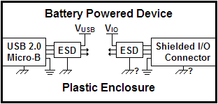
Box Diagram

I'm assuming that grounding the USB connector and it's ESD array to the chassis ground is the right way to go, but should I also ground my I/O connector and it's ESD array to the chassis ground? If the device was running on USB power, the chassis ground would be connected to earth through the host PC. But if the device was running on battery power, the chassis ground would be floating. In this case, should the chassis ground be connected to the system ground somewhere? Wouldn't this cause some of the ground current to flow through the USB cable when it's connected?

\$\endgroup\$

1 Answer 1

2
\$\begingroup\$

[ At the moment, this is a half-answer-half-comment. I intend to evolve it into a full-blown answer as more information becomes available from the O.P. ]

Here are a few points. They connect some of the dots, but not all of them.

  • USB shield is left unconnected on the device side, because it's always connected on the PC side. (There is a variant where USB shield is connected through a capacitor on the device side to provide a path for high-frequency signal.)

  • ESD arrays are always between an external terminal and the ground of the circuit that's being protected (signal ground, digital ground).

  • It's possible to get into a situation where you have current flowing through shields. It can adversely affect measurements. There are 2 options for dealing with this.

    • Provide galvanic isolation which would prevent the current from flowing.
    • Make measurements only when powered from a battery. Put a note into the manual. Enforce it in firmware.

The remaining question is: Where to connect the shield of the sensors cable? It depends on the nature of the what's being measured. For example, if the target is earthed, then the connecting the shield to the target's earth is good for reducing EMI. Please tell us more about what you are measuring and about the surrounding EMI environment. (?)

\$\endgroup\$
2
  • \$\begingroup\$ The "sensors" will be smart devices that will measure things like temperature or conductivity. They'll take care of any necessary isolation, the link is purely digital. \$\endgroup\$
    – Neil
    Commented May 1, 2015 at 17:21
  • \$\begingroup\$ I'm not sure the first and second bullet points make sense to me... Would you not want to connect the USB shield to the chassis on the device side? Also, wouldn't an ESD strike directed down the USB ground wire cause the ground line to bounce and reset the system? \$\endgroup\$
    – Neil
    Commented May 1, 2015 at 17:23

Your Answer

By clicking “Post Your Answer”, you agree to our terms of service and acknowledge you have read our privacy policy.

Not the answer you're looking for? Browse other questions tagged or ask your own question.