3
\$\begingroup\$

What tradeoffs and connection options are there in low cost bidirectional communication between just two microcontrollers?

In this case:

  • Master/Slave relationship, bidirectional data flow
  • Distance under an inch
  • Slave plugs into the master (so ESD protection on the connections is a must).
  • The slave micro is pretty dumb, but medium speed data is needed for block I/O from a SD card. Other than the SD card, there is a bit of low speed I/O on the slave unit where speed is not an issue.
  • Cheap cheap cheap.
  • Pin count is restricted.
  • Prefer minimum protocol stack overhead.

Obvious options include SPI, CAN, USB, TTL Level Serial. I2C and 1-Wire are probably too slow. Because of the pin count issue modulating the power supply for data would be ideal, if there were a consumer level chipset that did it, saving two pins over the serial methods.

\$\endgroup\$
5
  • 1
    \$\begingroup\$ What do you mean by "medium speed data"? Do you have an order of magnitude in mind? 100kb/s? 1Mb/s? Do you have constraints on which MCU you want/need to use? When you say master/slave do you want to support bidirectional transmission? Or just want to "throw" data at the dumb slave without any form of error correction scheme or feedback? \$\endgroup\$ Commented May 6, 2015 at 23:03
  • 1
    \$\begingroup\$ "low cost" and "simple" and "modulating the power supply" do not go together. I've done work on differential manchester encoded serial data over a 12V and GND power supply connection, and it's not fun in both software and hardware, so don't even bother with that avenue! \$\endgroup\$
    – KyranF
    Commented May 6, 2015 at 23:41
  • \$\begingroup\$ @LorenzoDonati By "medium speed data" I mean saving encoded video to an SD card, so maybe 5 MB/s. \$\endgroup\$
    – Bryce
    Commented May 7, 2015 at 8:22
  • \$\begingroup\$ @KyranF modulating the power supply would only work if some Made in China IC existed that handled everything. \$\endgroup\$
    – Bryce
    Commented May 7, 2015 at 8:22
  • \$\begingroup\$ Fair enough. There probably is one which partially does it, but would still rely on plenty of custom external circuitry \$\endgroup\$
    – KyranF
    Commented May 7, 2015 at 15:36

6 Answers 6

14
\$\begingroup\$

Given your available options, it appears that you do have some pins available:

  • SPI is full-duplex and requires 1 clock + 1 data each direction + 1 optional chip select = 3 pins
  • CAN is half-duplex and requires 2 data for bidirectional comms = 2 pins
  • USB is half-duplex and requires 2 data for bidirectional comms = 2 pins
  • TTL Serial is anything you want, but most people use a UART for it, requires 1 data each direction = 2 pins full duplex or 1 pin with some trickery
  • UART is full-duplex and requires 1 data each direction = 2 pins or 1 pin with some trickery
  • I2C is half-duplex and requires 1 clock + 1 data = 2 pins

So it looks like the consensus is 2 pins if you want bidirectional communication, or possibly 3 for SPI. Given equal pin counts, I'd go for the UART if there's one available on both chips. Assuming a 1:1 connection, you can just toss data across without regard for timing or collisions, and the hardware is really easy.

As for the stack overhead, there are many different protocols that can operate from a UART, but it's probably best in this case to define your own. From the comms' perspective, you're just spewing out bytes and receiving them at the other end. The hardware will sync itself to each byte automatically, but you still have to know which byte is what. You'll have that problem regardless of which option you choose.

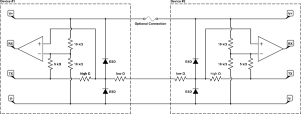
If you're clever with a UART (and I'm about to give you the answer), you can connect the two TX pins together with two resistors in series, then have a comparator on each end that drives the RX pin based on the local TX and the center tap of the two resistors. This allows full-duplex on one wire. See below for a schematic.

For ESD, add a series resistor inside both cases for each pin and put some clamping diodes on the outboard side of the resistor. There are diodes specially made for this.


schematic

simulate this circuit – Schematic created using CircuitLab

  • The "low" resistors are to protect the ESD diodes. Datasheets may or may not claim that they're unnecessary, but I'd use them anyway. Make them just big enough to do their job; they need to look like a short compared to the "high" resistors.
  • The "high" resistors are to mix the two TX signals on the common wire.
  • The 10k and 5k resistors are to take the full-supply-range TX signal and provide the appropriate threshold for the comparators.
  • If the two devices are powered independently, you probably shouldn't have the "Optional Connection", leaving you with 2 wires instead of 3. I don't see how you can communicate at all with fewer pins than this, unless you go wireless.

Here's how it works:

  • If both TX's are high, the common line will be high and both comparators will output high.
  • If both TX's are low, the common line will be low and both comparators will output low.
  • If one TX is high and the other low, the common line will be mid-range and each comparator will have a different threshold based on its local TX. So the one with a high TX will have a higher threshold than the mid-range common and will output low, and the one with a low TX will have a lower threshold than the mid-range common and will output high.

So in all cases, the receiving comparator output equals the sending TX.

If you don't like the hardware complexity inside the box, then you can use a discrete pin for each direction and keep only the "high" and "low" resistors and ESD diodes - a separate copy for each pin.

\$\endgroup\$
0
6
\$\begingroup\$

I've never used CAN bus so I can't comment on that. Which leaves SPI, I2C, TTL serial and USB.

TTL serial is usually clocked at 115,200 baud, but many microcontrollers can run it at 1 Mb/s or higher. You'll have to check your microcontroller's datasheets and see if you can run it that fast. Obviously both ends must match. The advantage for TTL serial is that it requires only two wires.

I2C originally was limited to 100 Kb/s, then 400 Kb/s. The latest standard is 1 Mb/s. But it's possible your microcontroller can be clocked higher than that. Again, check your datasheets. Like TTL serial, I2C only requires two wires.

SPI is a whole different breed. Theoretically, it can run up to 50 Mb/s or so. I've run one with an SD card in a commercial product at 25 Mb/s without any problems. The downside is the SPI interface requires four wires. Actually, with just one slave on the bus, you don't need the chip select line unless it is required by the hardware interface. If you are only sending data to the slave, you might also be able to get rid of the MISO line, if the microcontroller lets you reassign it as a GPIO pin. In the case you're down to two wires, like the others.

Firmware overhead for the first three is minimal; TTL serial is probably the simplest. I2C and SPI are about the same.

You can forget about USB, even though it is potentially the fastest if you run USB 2.0. (USB 1.1 is only 12 Mb/s so it doesn't even compare favorably with SPI as far as speed.) The first problem with USB is you need to implement a host on one side and a slave on the other. This requires microcontrollers that have the interfaces, and USB host interfaces are generally only found on fairly high-end chips, Then there's the firmware required. Several kB of firmware. Good news is you can generally get a library from the manufacturer. Bad news is it will still take you weeks to get it working.

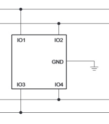
You'll have to provide your one ESD protection on the interfaces. There are lots of cheap chips that perform this function, like the TPD4E1B06 for 61ȼ at Digi-Key.
enter image description here

\$\endgroup\$
2
  • \$\begingroup\$ About CAN: It's a bus system like I²C. While I²C is made for communication on one PCB, CAN allows up to 2km distances. Therefore, it has lots of protocol overhead, as a CAN message contains up to 64 data bits, but also about 50 bits for message ID, address, CRC and so on. I²C also "wastes" some bits for adressing, but not so much. It may also add some programming overhead. So, definitively, no CAN here! \$\endgroup\$
    – sweber
    Commented May 7, 2015 at 11:01
  • \$\begingroup\$ 61 cents is not cheap to the level required. With pick and place individual zenders start to look cheap. \$\endgroup\$
    – Bryce
    Commented May 7, 2015 at 18:32
2
\$\begingroup\$

Have you considered UART? For unidirectional communication, only one wire is needed. If you'll be sending large chunks of data, you can get clever and have the single wire alternate between TX and RX according to some made-up rules. You can build your own protocol to handle error correction, bus contention and so forth. The nice thing is that even the cheapest MCUs will have built-in UART (the same can't be said for USB or CAN).

If you look you can probably find power supply modulation schemes, but their datarates will likely be much slower.

\$\endgroup\$
1
\$\begingroup\$

Based on your statement "Because of the pin count issue modulating the power supply for data would be ideal, if there were a consumer level chipset that did it, saving two pins over the serial methods", it sound like 1-wire communications however it does provide low speed data and you do not state what your speed requirement might be.

\$\endgroup\$
1
  • \$\begingroup\$ Added speed requirement above, which is controlled by the SD card requirement. \$\endgroup\$
    – Bryce
    Commented May 7, 2015 at 8:33
1
\$\begingroup\$

I don't see much sense in a master/slave system with just two µC that both are programmed by yourself.

The smallest pinout you can get is probably UART (2pins). Since you're programming both µCs, you can choose an arbitrary speed. An AVR µC could run UART at 1Mbps, and assuming you choose 1 stop bit, no parity, and 9 data bits you can get 82% bandwidth utilisation.

You can always bit-bang a custom protocol similar to 1-Wire (but much faster). However that is a rather silly approach as it would consume all your processing power on maintaining the protocol.

\$\endgroup\$
1
\$\begingroup\$

TLDR: Not particularly cheap but reliable fit in some use cases.

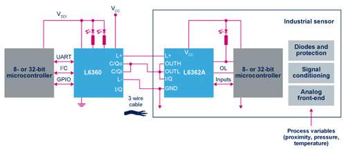
Looking outside the box, there might be some other solutions here such as following chip that I bumped into lately. Of course, it all depends on what you want to do. Something like UART comes to mind if you got them both MCUs on the same board or even planning to ESD protect them manually if separated.

Master and Device Solution for IO-Link Applications

L6360   Master
L6362A  Device

enter image description here

When would you consider a solution such as this:

  1. The frontier chips come Fully protected which would be important if you have each MCU on a separate board and dealing with exposed pins e.g. screw terminal.
    • Reverse polarity
    • Overload with cut-off function
    • Overtemperature
    • Undervoltage and overvoltage
    • GND and VCC open wire
  2. Interoperability. If somebody else is going to design the other side all he needs to know is to funnel the data through IO-Link.
  3. Integrated regulator Vcc(in) 7~30v, Vdd(out) 3.3/5v

It sounded interesting to me, so I thought I'll put it out there.

\$\endgroup\$

Your Answer

By clicking “Post Your Answer”, you agree to our terms of service and acknowledge you have read our privacy policy.

Not the answer you're looking for? Browse other questions tagged or ask your own question.