3
\$\begingroup\$

I am trying to design a circuit and was wondering how to design it that the 12V 800mAH NimH battery I am using will not overcharge. I have researched trickle charging and as far as I understand, a zener diode that regulates the voltage down to about 13.3-13.7V should do. I chose a 14V Zener, taking into account the .6-.7V drop.

I have heard that trickle charging is not the best for the battery, but am not sure how much more work designing a smart charger would take.

I was also thinking of using another diode to prevent flow back to the panels from the battery.
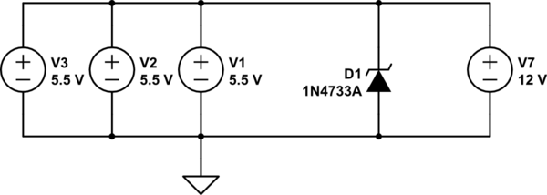
schematic

simulate this circuit – Schematic created using CircuitLab The three voltage sources on the left represent the solar cells, with the NiMH battery on the right.

I was wondering if I needed any additional components if I were to use three 5.5V solar cells in parallel outputting 40mA (16.5V total at 40mA, regulated to 13.3V by the zener) in order to prevent overcharging.

A similar question to mine was asked at How do I avoid overcharging a battery? However, this dealt more with a larger lead-acid battery and used a voltage regulator with a schottky diode.

Smart charging circuit for NiMH battery pack This link discusses almost my exact same question, but I was confused to the answer given which said that up to 1.45V per cell could be charged, taking my max charge voltage up to 14.5V.

Considering I am only outputting 40mA to an 800mAH battery, it seems that I may not need any more battery protection, but would love any input.

\$\endgroup\$
4
  • \$\begingroup\$ Hi, Jacob. Thanks for visiting this forum! There are several problems with your question. First, Can you provide a link to the actual solar cells you are using? They generally have a Voc and Isc rating. Voc = open circuit voltage, and Isc = short-circuit current. There may also be a peak power voltage specified. All these will be helpful. Second main thing is that the solar panels in your schematic are drawn in parallel, not in series. When put in parallel, the currents add and the voltage is the same as one unit. So you should probably redraw the schematic to put them in series. \$\endgroup\$
    – user57037
    Commented May 9, 2015 at 22:48
  • \$\begingroup\$ Also, a reverse-biased zener does not have a ".6-.7 volt drop". You're thinking of the voltage drop for a forward-biased diode, and that doesn't apply here. \$\endgroup\$ Commented May 10, 2015 at 1:41
  • \$\begingroup\$ Here are the panels: store.sundancesolar.com/5-5v-40ma-solar-cell. They have an open circuit voltage of 6.5V and Isc is 44mA \$\endgroup\$ Commented May 10, 2015 at 13:33
  • \$\begingroup\$ Would I use the open circuit voltage rather than peak voltage when calculating resistor value as tcrosley described below? \$\endgroup\$ Commented May 10, 2015 at 13:37

1 Answer 1

4
\$\begingroup\$

First of all, you have the three 5.5 V solar cells in parallel. They need to be in series to generate 16.5 V.

NiMH batteries are usually charged using special IC's made for this purpose since they require special monitoring. However at the low level of current you have available (40 mA) you can get by with a much simpler charger as mentioned here. You need to make sure the current doesn't go above this level (it needs to be below 0.05C, where C = 800 mA). If the current does go above this, up to C/10 (800 mA), then you need to add a timer so the charging cycles is not more than 3 hours.

You need to replace the 5.1 Zener with a 12 V one, such as the BZX85C12. In addition, you will need to add a 110 Ω resistor between the output of the solar cells and the Zener. The value is calculated by dividing the voltage drop 16.5 V - 12 V by the full-load current of 40 mA. At no load, the Zener will dissipate 0.04 A * 12 V = 500 mW, or half the maximum rating (1 W) of the diode.

\$\endgroup\$
2
  • \$\begingroup\$ Ah, confused my panels, thanks for the correction. So even though the battery can be charged up to ~13.3V I would still use a 12V Zener? \$\endgroup\$ Commented May 10, 2015 at 13:20
  • \$\begingroup\$ @JacobRiggs I assume you will be feeding the battery into a load most of the time. If it can tolerate the 13.3v then you can use the higher voltage Zener. I would choose 1 13v one, such the NZX13A. You should reduce the value of the resistor to 91 Ω. \$\endgroup\$
    – tcrosley
    Commented May 10, 2015 at 18:37

Your Answer

By clicking “Post Your Answer”, you agree to our terms of service and acknowledge you have read our privacy policy.

Not the answer you're looking for? Browse other questions tagged or ask your own question.