0
\$\begingroup\$

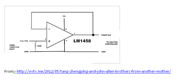
Making a LM1458 work as a Unity Gain buffer with an input of 0 to 12v output to a digital voltmeter.

Unity Gain Buffer

When I connect this cct to the injector timer (voltage) & a Voltmeter to the output the voltage stays at about 2.0V until the input exceeds that. I tried to bias the input but it made little difference. I swapped ic's with the same result. The source resistance is about 190k, the Voltmeter input impedance is about 125k Ohms. The reason for the buffer is because the Voltmeter sinks the source voltage too much. How do I get the input Sensitivity to start at least as low as 0.1V up to 12V, output to follow suit.?

\$\endgroup\$
3
  • \$\begingroup\$ The 100k & the input & output labels are not my application. Supply is Alternator voltage as this circuit only activates when engine is running. \$\endgroup\$
    – JohnP4216
    Commented May 14, 2015 at 8:51
  • \$\begingroup\$ Measure the current when throttle is connected to ground (through an ammeter). \$\endgroup\$ Commented May 14, 2015 at 13:06
  • \$\begingroup\$ WhatRoughBeast has already given you an answer. One such inexpensive single supply capable rail to rail op amp that should work is TLV272. It even has the same pinout as the LM1458. \$\endgroup\$
    – rioraxe
    Commented May 15, 2015 at 7:36

4 Answers 4

1
\$\begingroup\$

The answer to your question is very simple, and it comes in 3 parts:

1) you can't do it with that op amp,

2) you need an op amp with rail-to-rail inputs and rail-to-rail outputs, and

3) don't believe everything you read on the internet.

Take a look at the data sheet http://www.ti.com/lit/ds/symlink/lm1458.pdf At the bottom of page 2 you'll see "Output Voltage Swing". For a power supply of +/- 15 volts, you can't count on getting better than +/- 12 volts. In other words, the output will only drive to within about 3 volts of the negative supply. Does that sound familiar?

\$\endgroup\$
3
  • \$\begingroup\$ Thanks for your incites & poss solutions. I have used this Opamp for many applications before & not had the issue of not getting sensitivity close to ground before. If I can get a swing to 10V that would be adequate as it would represent an injector ON time of over 80% which will probably never be achieved on my sprinter Diesel. The highest I observed on my Skyline where this unit was previously fitted was of the order of 55%. Normal driving should be in the 5 - 15% range. 0.3V to 8.0V should give me 1% to 60% injector ON time. Adequate to graph the vehicle economy curve, the project purpose. \$\endgroup\$
    – JohnP4216
    Commented May 14, 2015 at 23:03
  • \$\begingroup\$ In response to 1) Can you suggest a more suitable single rail Op Amp. \$\endgroup\$
    – JohnP4216
    Commented May 15, 2015 at 8:26
  • \$\begingroup\$ Actually, your selection is somewhat limited by your relatively high power supply voltage. Most rail-to-rails work with rather lower voltages. However, the LT1677 linear.com/product/LT1677 would do for you. It's a bit expensive ($5 at Digikey) but if you only need one you should be OK. \$\endgroup\$ Commented May 15, 2015 at 13:06
0
\$\begingroup\$

Previous answer is correct. However, there may be a solution to this. Your V+ is connected to +15V. Your V- is connected to 0V. Hence your output voltage swing can't go as low as 0V. If you apply a negative voltage to V- (pin 8) of -3V or below, then you should be able to get your output voltage to drop down to 0 volts. You can do this with a couple of resistors acting as a potential divider. Use two reistors in series.

 ---V15V  -> ..pin 8.. V+ of LM1458
 |

 R

 |------- > OV point (GND)

 R
 |

----- V0V -> ..pin 4... V- of LM1458

Make R a fairly large value so you're not draining too much current from the supply. Make the 100K resistor connect to the GND in the diagram above.

The opamp is still being fed with a difference of 15V between V+ and V-, but V0V is now 7.5 voltages below GND.

Something like this ought to work. I did something similar with a 741 op amp configured as a wien bridge oscillator fed from a 9 volt battery. The key is recognising that the battery is 9 volts potential difference between the terminals, but you can share that 9 volts across two equal sized resistors to give 4.5volts difference across each. And then make your centre point of the resistors your 0V (a 0V common). Voltages are relative, they're all differences between two points.
\$\endgroup\$
2
  • \$\begingroup\$ Note that this is an automotive application, not a lab setup. The power supply is the 12volt battery, and this is by definition connected to ground as the -. There is no way to float the circuit other than by using a DC-DC converter. \$\endgroup\$ Commented May 14, 2015 at 15:38
  • \$\begingroup\$ The source voltage reference is to Ground. The Voltmeter voltage ref is to Ground (it is a 12V powered 3 digit LED meter with a common ground for the sense lead). The current display is 2 LM3914 bargraph. 1st goes 0 to 10% the 2nd 20 to 100% in 10% increments which is too steppy, thus the voltmeter. \$\endgroup\$
    – JohnP4216
    Commented May 14, 2015 at 23:27
0
\$\begingroup\$

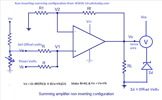
Here is a circuit suggestion to create the necessary input offset to get the Output data I want. The Output has also been referenced to the offset to effectively subtract the input jump.enter image description here

\$\endgroup\$
0
\$\begingroup\$

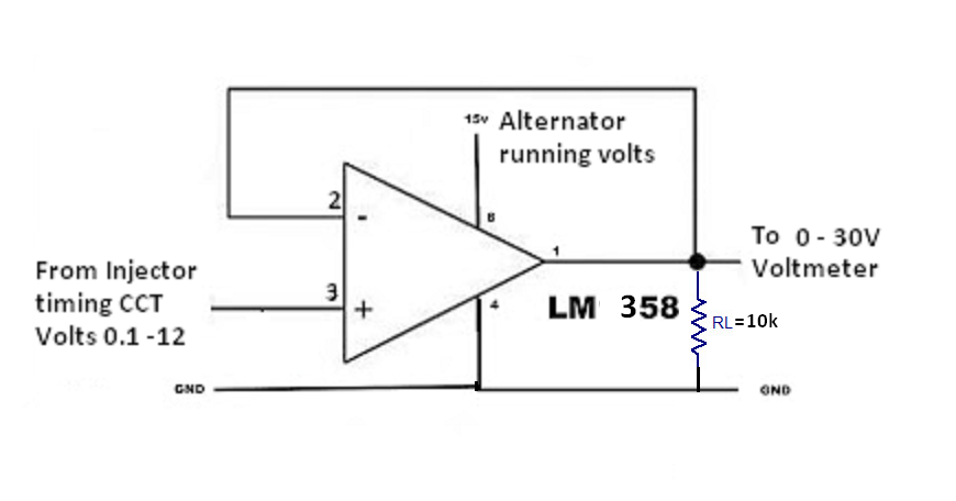
enter image description here@WhatRoughBeast, @Dean The blue circuit above works, the only amendment was to replace Zd with a yellow LED & link its 2.1V ref back to the summing input instead of the separate voltage divider. However in the end I decided to use a LM358 which is designed for a single sided power supply. Needs almost no additional components as per the 1st post circuit. For anybody ending up here for reasons as I did it would benefit to read Application Note 116 (AN-116) from TI or National Semiconductor available from http://docslide.us/documents/lm358.htm. The best answer is the LM358. Thanks guys.

\$\endgroup\$

Your Answer

By clicking “Post Your Answer”, you agree to our terms of service and acknowledge you have read our privacy policy.

Not the answer you're looking for? Browse other questions tagged or ask your own question.