1
\$\begingroup\$

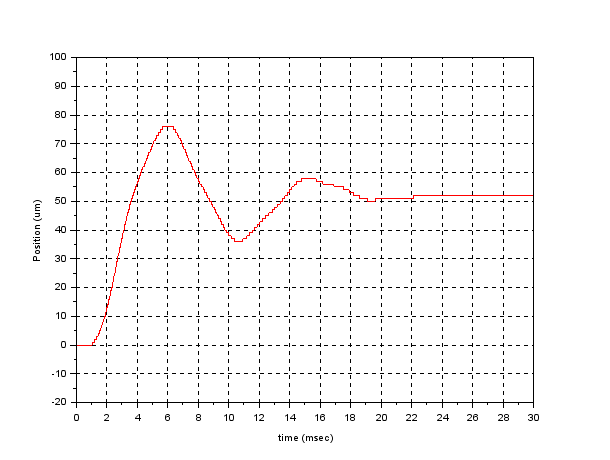
I'm working on a system involving a stepper motor that is used for moving a carriage back and forth in a linear motion. I have recorded the response (i.e. carriage position vs. time) corresponding to a single motor step. This, I believe, is what one would call the impulse response of the system:
enter image description here

In order to simulate the response to several consecutive steps, and to develop speed control strategies, I'm looking for a way to convert this time-domain impulse response into a frequency-domain (Laplace) transfer function of the form num(s) / den(s), if possible using open-source tools like Scilab or Python. What's a pragmatic way to do that?

\$\endgroup\$
5
  • \$\begingroup\$ This would be a step-response which the impulse-response can be calculated. An approach, is to convert the step-response to an impulse-response and then take the transform. \$\endgroup\$ Commented Jun 5, 2015 at 12:49
  • \$\begingroup\$ I am sure this has already been asked but I can't find the other question. That's a second order response, your fundamental frequency is about 100Hz (measure it on the graph) while the Q factor is a bit trickier, especially with so few oscillations. \$\endgroup\$ Commented Jun 5, 2015 at 12:56
  • 1
    \$\begingroup\$ electronics.stackexchange.com/questions/117124/… \$\endgroup\$ Commented Jun 5, 2015 at 12:56
  • \$\begingroup\$ Of course you need to calculate also the DC gain but that's pretty obvious :D \$\endgroup\$ Commented Jun 5, 2015 at 12:57
  • \$\begingroup\$ Chris: this is the response to a motor step, which is actually a discrete event. There's no way I can move the carriage more than a motor step (approx. 50 um) at a time, which is why I was thinking of this as an impulse reponse. \$\endgroup\$
    – geschema
    Commented Jun 5, 2015 at 13:07

2 Answers 2

1
\$\begingroup\$

What you call the response depends on what you decide the input to the system is. You can't treat the SM in isolation as it needs a driver, and that will have logic-level direction and 'pulse' inputs. So if, e.g., you define the input to the system to be a required displacement of 50um, the steady-state output will be 50um and your graph will be a step response. From this graph, the system has unity steady state gain and you can work out the transfer function from the overshoot and time to 1st peak etc.

This Laplace transfer function represents the unit impulse reponse of the system (i.e., the inverse LT of the transfer function is the unit impulse response).

There will be, inevitably, a computer somewhere in the loop and this will take care of the change of variables between actual displacements in um and the logic-level signals needed to control the SM driver.

From your graph, %overshoot=50%, Tp = time to 1st peak =5ms, therefore damping coeff is about 0.2, and Wn approx =640 rad/s (=about 100Hz); hence approx TF:

G(s)=411200/(s^2 + 256s + 411200)

\$\endgroup\$
1
\$\begingroup\$

This looks most as rotor stabilizing in new position or maybe the belt does the same. Either way i can't imagine, why do you need transfer function in open loop system. Just adjust speed and acceleration.

\$\endgroup\$

Your Answer

By clicking “Post Your Answer”, you agree to our terms of service and acknowledge you have read our privacy policy.

Not the answer you're looking for? Browse other questions tagged or ask your own question.