3
\$\begingroup\$

I'm starting to investigate Altera's Cyclone IV FPGA to use in my projects. Now I borrowed from neighboring company a real device with USB Baster Rev.C. I'd try to use one instead of evaluation board which I don't have for the moment.

Before I will put any code into the device I'd like to download original firmware to make me possible to return the device to it's initial state at any moment.

However after I connected USB Blaster to the device via JTAG and run Programmer I did not find any "Read" button (as I usually see on AVR programmers GUIs):
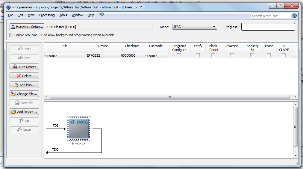
enter image description here

Brief search in Internet did not help.

EDIT 1

It looks like there are additional memories on the board:
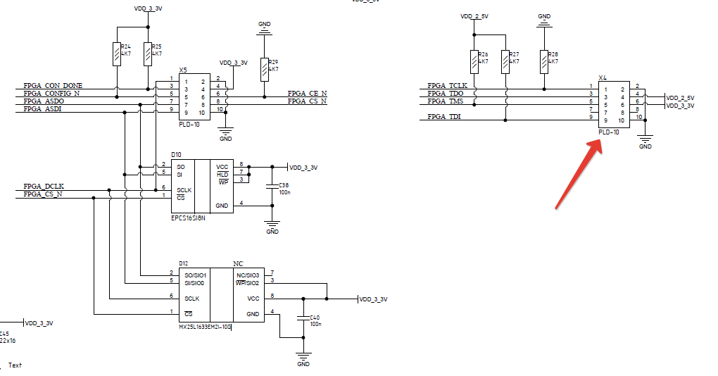
enter image description here

I used to connect via X4 (pointed with a big red arrow).

\$\endgroup\$
2
  • \$\begingroup\$ How is the device connected to it's flash chip? JTAG? Active Serial? Passive Serial? Parallel? \$\endgroup\$
    – sbell
    Commented Jun 8, 2015 at 11:08
  • \$\begingroup\$ @sbell please see my EDIT 1 for clarification. \$\endgroup\$ Commented Jun 8, 2015 at 12:29

3 Answers 3

3
\$\begingroup\$

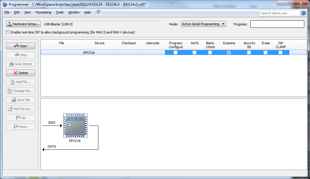
To read the device configuration, you have to connect to X5 instead of X4 (as pointed out by @Simon Richter). Change your settings to match what is shown below:

ready to examine configuration

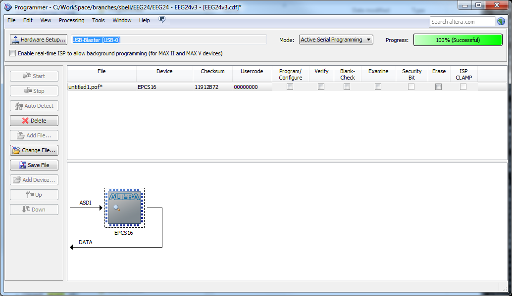
Click "Start" to read the configuration. When it finishes, you can set a file name and then click "Save File" as below:

ready to save configuration

\$\endgroup\$
5
  • \$\begingroup\$ Thank you for the answer! I don't have the device by me right know, but AFAIR when I connected USB-B to X5 it wasn't able to detect any device at all. I will try again more accurately on Wednesday and post a new comment! Thank you for your input again! \$\endgroup\$ Commented Jun 8, 2015 at 16:01
  • 2
    \$\begingroup\$ Just make sure that you have the mode set as "Active Serial Programming", and that the device appears as "EPCS16" -- just like the images above show them \$\endgroup\$
    – sbell
    Commented Jun 8, 2015 at 16:58
  • \$\begingroup\$ You're awesome, guys! Thank you very much for the help! \$\endgroup\$ Commented Jun 10, 2015 at 8:31
  • \$\begingroup\$ In which format does the "save file" option saves the Examine data. Is it .rpd or .sof or .pof or .hex or .jic? EPCS needs .rpd format right! \$\endgroup\$ Commented Dec 7, 2017 at 9:22
  • \$\begingroup\$ It saves as a .pof file which works just fine for an EPCS. If you do need a different format though, you can save the .pof first and then convert it using File->"Convert Programming Files..." \$\endgroup\$
    – sbell
    Commented Dec 7, 2017 at 20:31
2
\$\begingroup\$

There is no way to read back the current configuration.

If your development board is wired for JTAG mode, as it looks like from your screenshot, then simply writing a new configuration will update the FPGA only and leave the configuration flash alone, so a power cycle will reload the flash and everything is back to as it was before.

\$\endgroup\$
2
  • \$\begingroup\$ This is something new for me as I assumed that modern microcontrollers (at least for last 10-15 years) has everything on a board: memory, IOs, timers and so on. So I assumed that Altera's FPGAs are the same. Please see my EDIT 1 for some clarification regarding your counter-questions. Thank you for your attention! \$\endgroup\$ Commented Jun 8, 2015 at 11:57
  • 3
    \$\begingroup\$ The FPGA has the SRAM for the tables, but the contents for the tables are loaded from an external flash chip (EPCS...) . If you connect to the JTAG connection (as you do), you can update the SRAM, which is volatile. If you connect to the serial bus on X5, you can overwrite the flash and then reset the FPGA with the /CS and /CE pins. \$\endgroup\$ Commented Jun 8, 2015 at 12:12
0
\$\begingroup\$

I don't know whether you can read or not via Quartus II the configuration as it is and let Quartus II translate you in VHDL/Verilog what was stored in the memory. One thing that can always be done is to read the content of your EPCS memory with a SPI reader, make the whole dump. Well, considering the memory space (>=16MB), you will more than probably create a MASSIVE .hex file. There are file splitters on the internet and as long as the .hex file is quite straightforward, you can directly read the split file with Notepad++ or Hexedit (better solution for raw files) for example. Maybe 128kbytes every single split file, or 256 tops, can be a correct volume. In theory, you wouldn't need to power the whole board, but only the EPCS Chip. By the way, maybe an Arduino correctly programmed can create the dump on an external microSD card provided you have one and the correct shield.

If it is only for a copy/paste of the configuration memory, it shall do the trick. I want to do that for my DE10-Nano kit. Hem, I have everything I need to do so : Arduino, mem card, shield, wires... I will probably try soon.

If it is for a reverse engineering, I wish you the best of luck!

\$\endgroup\$

Your Answer

By clicking “Post Your Answer”, you agree to our terms of service and acknowledge you have read our privacy policy.

Not the answer you're looking for? Browse other questions tagged or ask your own question.