1
\$\begingroup\$

I have a question about the regulation accuracy (or lack of) of a 3V6 Zener diode. I wanted to confirm that I wasn't doing anything stupid.

I set up the standard test circuit shown below.
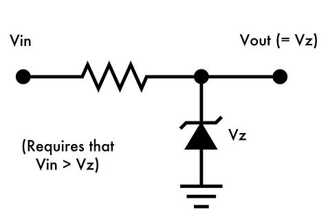
enter image description here

No load except for the DMM. The two Zeners in question are: BZX55C3V6 (3V6 - 500mW) and 1N4729A (3V6 - 1W). Both Zeners came from separate suppliers. \$V_{CC} = 5\$V and is relatively stable (total variance no more than 40mV). I know that Zeners need a minimum current to regulate properly and I worked out the optimum current through the combination of \$I_{zt}\$ from the datasheet and the following "rule of thumb" calculation: $$I = \frac{(P/V) \times .7}{4}$$

Taking the 1N4729A as an example, the \$I_{zt}\$ is roughly 70mA. Working out the current limiting resistor we have: $$\frac{5 - 3.6}{70\text{mA}} = 20\Omega$$

When I tested the zener with a \$20\Omega\$ resistor I get a \$V_z\$ of just over 4V! In fact, as I increase and decrease the resistor value, the Zener voltage increases and decreases along with it. It's like the Zener resistance isn't decreasing as the current increases, which is not what I'd expect. What's odd is that the BZX55C is showing more-or-less the same behaviour although with different resistors. Is this normal?

\$\endgroup\$
2
  • \$\begingroup\$ can you try with higher input voltages? The dynamic resistance of the Zener may not be able to drop low enough, even with 70mA available to it, to make the proper resistor divider equivalent for the node to be equal to 3.6V. Also realize that Zeners are not exactly accurate over all temperature ranges \$\endgroup\$
    – KyranF
    Commented Jun 8, 2015 at 16:09
  • \$\begingroup\$ Try to find a datasheet for your specific zeners which shows the breakdown characteristics. In my experience, low-voltage zeners (anything below 5V) all seem to have a very soft 'knee' and not particularly 'vertical' current-vs-voltage curve. See Fig 2 in diodes.com/datasheets/ds18003.pdf for an example. \$\endgroup\$
    – brhans
    Commented Jun 8, 2015 at 16:49

6 Answers 6

1
\$\begingroup\$

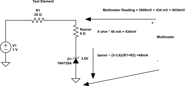
The problem is how you are modeling your circuit, because the series resistance you are using is so close the zener resistance, it must included in the circuit model. As shown in the circuit below which models the behavior that you are seeing of a voltage reading of about 4V from the zener diode

schematic

simulate this circuit – Schematic created using CircuitLab

\$\endgroup\$
6
  • 1
    \$\begingroup\$ I don't get it, where did the 9ohms come from? Is that the dynamic resistance of the zener? I suppose the point is, at 70mA, according to the datasheet, the voltage across the zener should be 3.6V, give or take 5%. It's not. \$\endgroup\$
    – Buck8pe
    Commented Jun 8, 2015 at 18:10
  • \$\begingroup\$ look at the 1N4729A datasheet, There is a Zz parameter specified at 9 ohms, This is the zener resistance, this is an intrinsic impedance to the device, in other words is part of the device. Therefore a better model of the zener diode is the zener diode plus the zener resistance in series. You do not see 3.6V accross the diode because as the picture show you are measuring the zener voltage plus the voltage drop assiocated with the zener resistance which together add up to be 4.035V \$\endgroup\$
    – Kvegaoro
    Commented Jun 8, 2015 at 18:26
  • \$\begingroup\$ Even if it specified at 70mA, there is going to be some there and in this case it is not negligible therefore it must be incorporated in to your circuit model, that why your circuit analysis provides a different answer but adding the zener resistance to the model gives a solution that approaches more closely your result. \$\endgroup\$
    – Kvegaoro
    Commented Jun 8, 2015 at 18:35
  • \$\begingroup\$ Actually, this does explain what I'm seeing and your result is pretty spot on with what I'm reading. \$\endgroup\$
    – Buck8pe
    Commented Jun 8, 2015 at 18:46
  • \$\begingroup\$ ittc.ku.edu/~jstiles/312/handouts/Zener%20Diode%20Models.pdf This link has an explanation on the The Zener Piecewise Linear Model. This is a more accurate model of an actual zener diode as compared to the "ideal zener" model \$\endgroup\$
    – Kvegaoro
    Commented Jun 8, 2015 at 18:49
3
\$\begingroup\$

A "zener" diode with a breakdown voltage below ~5.6V are based on the Zener effect and will have a very soft knee, I personally never use them.

The ones with voltage of 5.6 and above exploit the avalanche effect and have a very much sharper knee.

Even so I expect that the diode you have does match its data sheet.

For low voltage shunt regulation either use a series regulator (LDO) or a device such as the TL431 which has a band gap reference, and an opamp in a 3-poin package to create an almost perfect "Zener diode".

kevin

\$\endgroup\$
2
  • \$\begingroup\$ Actually, as it happens I had reached the same conclusion. This query was simply to highlight my dismay at how poor these zeners really are! Incidentally, reading the datasheet for the 431, I notice it says "When operated with enough voltage headroom (≥ 2.5 V) and cathode current (IKA)" in relation to the reference pin. Can I still get a reliable voltage if Vcc dips below 5V? \$\endgroup\$
    – Buck8pe
    Commented Jun 8, 2015 at 18:15
  • \$\begingroup\$ What output volta de you require? How much current will th load require? The closer to the minimum input voltage the more difficult it will be to avoid large changes in current flowing through the TL431. According to the Fairchild TL431 data sheet the dynamic resistance is only ~0.2ohm so it is much better than the zener. If you want to get 3.6v with a min input to 4.6V and 10mA current through the TL431 at min voltage this implies a 100 ohm series resistor. The output voltage will then change ~0.2/100 per volt of change on the input. i.e. 2mV, an attenuation of 500 times. Kevin \$\endgroup\$ Commented Jun 8, 2015 at 18:32
1
\$\begingroup\$

If you want decent accuracy throw the zeners away and use some low dropout 3.3V linear regulators. Zeners are notoriously power inefficient even at no load. At least at no load or very small load the LDO regulator will be way more efficient.

\$\endgroup\$
2
  • \$\begingroup\$ Indeed it would seem to be a much easier solution to just get an adjustable LDO, if this thing is meant to be used as regulated supply voltage. \$\endgroup\$
    – KyranF
    Commented Jun 8, 2015 at 16:30
  • \$\begingroup\$ Actually, it was a candidate for a regulated supply fed by a CCS. It isn't anymore:-) It seems to be all knee. \$\endgroup\$
    – Buck8pe
    Commented Jun 8, 2015 at 18:25
1
\$\begingroup\$

Rather than use rules of thumb which you may or may not understand, you should first look at the data sheet of the part you're using. From http://www.mouser.com/ds/2/427/bzx55-se-58740.pdf you will find that the BZX55C3V6 is tested at a current of 1-5 mA. Since you are driving more than 10 times that amount of current through it, it is no wonder that your voltage is high.

\$\endgroup\$
1
  • \$\begingroup\$ I didn't pass 70mA through the BZX55C, but the 1N4729A. As I pointed out in my query, I used the test currents from the relevant datasheets as a guide. \$\endgroup\$
    – Buck8pe
    Commented Jun 8, 2015 at 17:41
0
\$\begingroup\$

There are a couple of issues here. First this stated in the question: -

In fact, as I increase and decrease the resistor value, the Zener voltage increases and decreases along with it.

If you increase the resistor the voltage across the zener should go down.

Because it rises (as per the quote) you must have an unstable power source of 5V and this is rising as you increase the load resistance. Double check this supply.

The next problem is that at 70mA and 4 volts, the power is 0.28 watts and the self-heating may be causing the zener voltage to rise. I'm not sure what the temperature coefficient is for this device and the data sheets are lacking in that respect.

\$\endgroup\$
1
  • \$\begingroup\$ It seems odd then that the datasheets would specify an Izt of 69mA if it didn't show the zener in the best light. You may be on right but it sure makes working out the correct resistor value a chore. \$\endgroup\$
    – Buck8pe
    Commented Jun 8, 2015 at 18:21
0
\$\begingroup\$

If the 1W zeners were purchased from an unofficial channel they may, in fact, be something like 500mW units marked with the JEDEC 1N4729 number.

The 3.6V +/-5% @ 69mA is a JEDEC registered parameter and the voltage across the zener should be in that range (at Tj ~= 30°C) with 69mA flowing. 3.6V zeners typically have a negative temperature coefficient of -1.5 +/-0.5mV/°C, so self-heating will not account for the anomaly.

I suspect that if you retest the "1N4729" parts with a test current of something like 20mA (70 ohms) you may find that they're within spec voltage-wise.

The BZX55C3V6 is rated for 3.6V +/-0.2V at 5mA, so your resistor would be more like 280 ohms. You don't say what you saw there.

If you include the dynamic resistance in the model, you must use a lower voltage for the ideal zener. It's incorrect to add a voltage at the test current because of the dynamic resistance. The dynamic resistance describes the small-signal behavior near the test current.

Typically the dynamic resistance of the 1N4729A is about 5 ohms, so you could approximate it with an ideal 3.255V zener in series with 5\$\Omega\$ but only very near Izt = 69mA.

Zeners with nominal voltages less than 5V or so have very soft 'knees' (poor regulation) and are not really that useful as usually better alternative are available.

\$\endgroup\$
2
  • \$\begingroup\$ I see your (edited?) comment a little late. Can you expand on the statement: "It's incorrect to add a voltage at the test current because of the dynamic resistance". Does this conflict with what @Kvegaoro is saying? \$\endgroup\$
    – Buck8pe
    Commented Jun 9, 2015 at 12:46
  • \$\begingroup\$ Yes. That part of @kveagaro's answer is not correct. \$\endgroup\$ Commented Jun 9, 2015 at 13:00

Your Answer

By clicking “Post Your Answer”, you agree to our terms of service and acknowledge you have read our privacy policy.

Not the answer you're looking for? Browse other questions tagged or ask your own question.