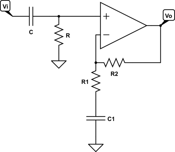
In the op-amp circuit you refer to, \$ C_1 \$ (there it's named \$ C_2 \$) is merely a de-coupling capacitor and is not intended for filtering.
I have never seen this circuit so I'd like to just calculate the transfer function and see where it brings us.
So, let's neglect \$ R \$ and \$ C \$ and assume the Op-Amp ideal, i.e. the voltage on the non-inverting pin equals that on the inverting pin and its input impedance is infinitely high.
Then in the frequency domain
$$ I_{R_2} = I_{R_1} = I_{C_1} = V_i/Z_1 = \frac{V_i}{R_1 + 1/j \omega C_1} = \frac{j \omega C_1}{1+ j \omega R_1 C_1} V_i = \frac{1}{R_1} \frac{j \omega R_1 C_1}{1 + j \omega R_1 C_1} V_i = \frac{1}{R_1} \frac{j \omega/\omega_1}{1 + j \omega/\omega_1} V_i $$
with \$ \omega_1 = \frac{1}{R_1 C_1} \$. Now we continue by writing the output voltage
$$ V_o = V_i + R_2 I_{R_2} = V_i + \frac{R_2}{R_1} \frac{j \omega/\omega_1}{1 + j \omega/\omega_1} V_i = \left[1 + k \frac{j \omega/\omega_1}{1 + j \omega/\omega_1} \right] V_i $$
with \$ k = \frac{R_2}{R_1} \$, and the transfer function is
$$ H(j \omega) = \frac{V_o}{V_i} = 1 + k \frac{j \omega/\omega_1}{1 + j \omega/\omega_1} = \frac{1 + j \omega/\omega_1 + k j \omega/\omega_1}{1 + j \omega/\omega_1} = $$
which for \$\omega = 0 \$ has a gain
$$ |H(0)| = 1$$
for \$ \omega = \infty \$
$$ |H(j \infty) = 1 + k $$
and for \$ \omega = \omega_1 \$.
$$ |H(j \omega_1)| = \left| 1 + k \frac{j}{1+j} \right| = \left| 1 + k \frac{j}{1+j} \frac{1-j}{1-j} \right| = \left| 1 + k \frac{1+j}{2} \right| = \left| 1+k/2 + jk/2 \right| = \frac{2}{k} \left| (1+2/k) + j \right| = \frac{2}{k} \sqrt ( 1 + (1 + 2/k)^2 ) = \frac{1}{\sqrt2 k} \sqrt(1 + 2/k + 2/k^2) $$
$$ = \sqrt(k^2/2 + k + 1) $$
I don't think the circuit does what it is assumed to do and the only way the cut-off frequency (where \$ \left| H(j \omega) \right| = 1/\sqrt2 \$) would be when \$ \frac{1}{k} \sqrt(1 + 2/k + 2/k^2) = 1 \$ or \$ k^2 + 2 k + 2 = (k+1)^2 + 1 = 1\$ and that would require \$ k = -1 \$, which is impossible with this circuit.
Edit:
After reading the link you gave, it appears there is a misunderstanding. It's about the non-ideal op-amp with bias current where \$ R \$ in your drawing should match \$ R_1||R_2 \$. If you adapt R to match this, you'll change the input decoupling circuit \$ R C \$ into a low-pass filter with the cut-off frequency \$ f = \frac{1}{2 \pi R C} \$, not \$ \frac{1}{2 \pi R_1 C_1} \$.

