Some background:
I am building a confocal fluorescence microscope. Long story short, photons are recorded using a Time Correlated Single Photon Counter (TCSPC). This TCSPC is capable of time stamping each individual photon.
Since the detector is a point detector, I "scan" a laser beam over the sample using galvo mirrors to image it and I correlate the position of my laser beam with the photon data.
Laser scanning is achieved by generating a wave form on an NI-USB6343 (specs in link) AO channel. At the start of each wave form period I also generate a pulse on one of the digital outputs of the NI device. This digital out is recorded by the TCSPC on a dedicated channel and serves as a reference to reconstruct the images. For this, the TCSPC has a dedicated channel.
The issue
I can do programming and chemistry but have zero knowledge on electronics.
APDs, TCSPCs etc... all operate on 50 Ohms (no idea why). The NI box is not particularly designed for that it seems and any 5V triggers generated by it are not registered by the TCSPC.
Connecting the digital out of the NI box to a scope using a 50 Ohm BNC cable with a 50 Ohm terminator on a T-splitter, I can indeed see that my pulses are not 5 V anymore but merely 1.5 to 2 V. All other aspects of my pulses (rise time) seem to correspond to the TTL spec.
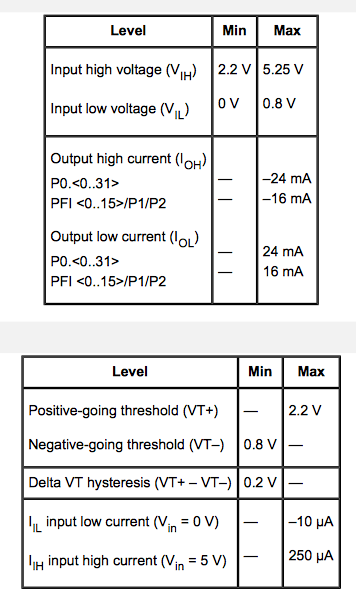
These are the relevant spect of the DO

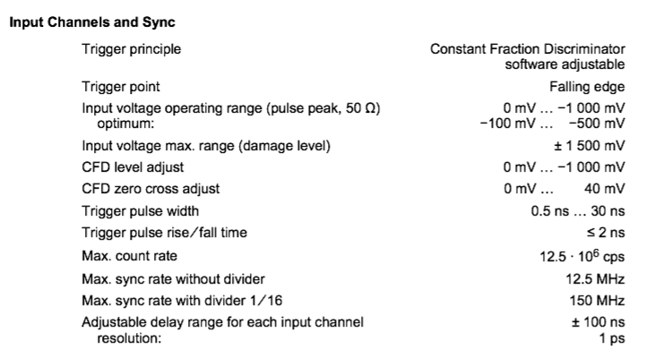
And this is the spec of the TCSPC:

Finally, the specs of the detector (of which pulses are being picked up by the TCSPC):

Since the TCSPC costs more than a luxury sedan, I'd like to get some feedback on the type of circuitry that might help to adapt the output of the NI box to the requirements of the TCSPC without the risk of damaging either.
I would also be helped by potential suppliers of such equipment or perhaps companies where I could order custom circuits to achieve my goal.
I have looked at posts like this but given I have zero knowledge of electronics let alone soldering skills, I couldn't make anything out of the supplied information...
Edit
As suggested in the comments, the TTL specs look like the device might be intended to receive negative voltage signals (and detect falling edges). However, looking at the provided manual, there seems to be a distinction between the signal inputs (to which I connect detectors and which have high time resolution) and the "low resolution" trigger inputs.
In the manual I found a specific description referring to them:

So there is a reference to a NIM style connector (NIM seems to predate TTL with True−16 mA into 50 ohms = −0.8 volts) but it clearly says "TTL in". So I assume that those M1 to M4 channels should accept "standard" TTL, i.e. positive voltage signals.
Moreover, most movable stages or salvo scanners indeed provide real TTL triggers to indicate "start of line" or "start of frame" events while raster scanning an image area...

