7
\$\begingroup\$

enter image description here enter image description here enter image description here

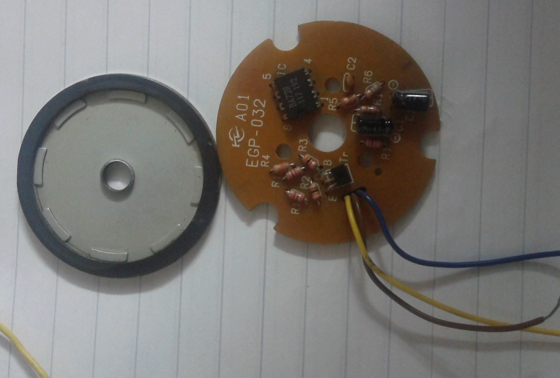
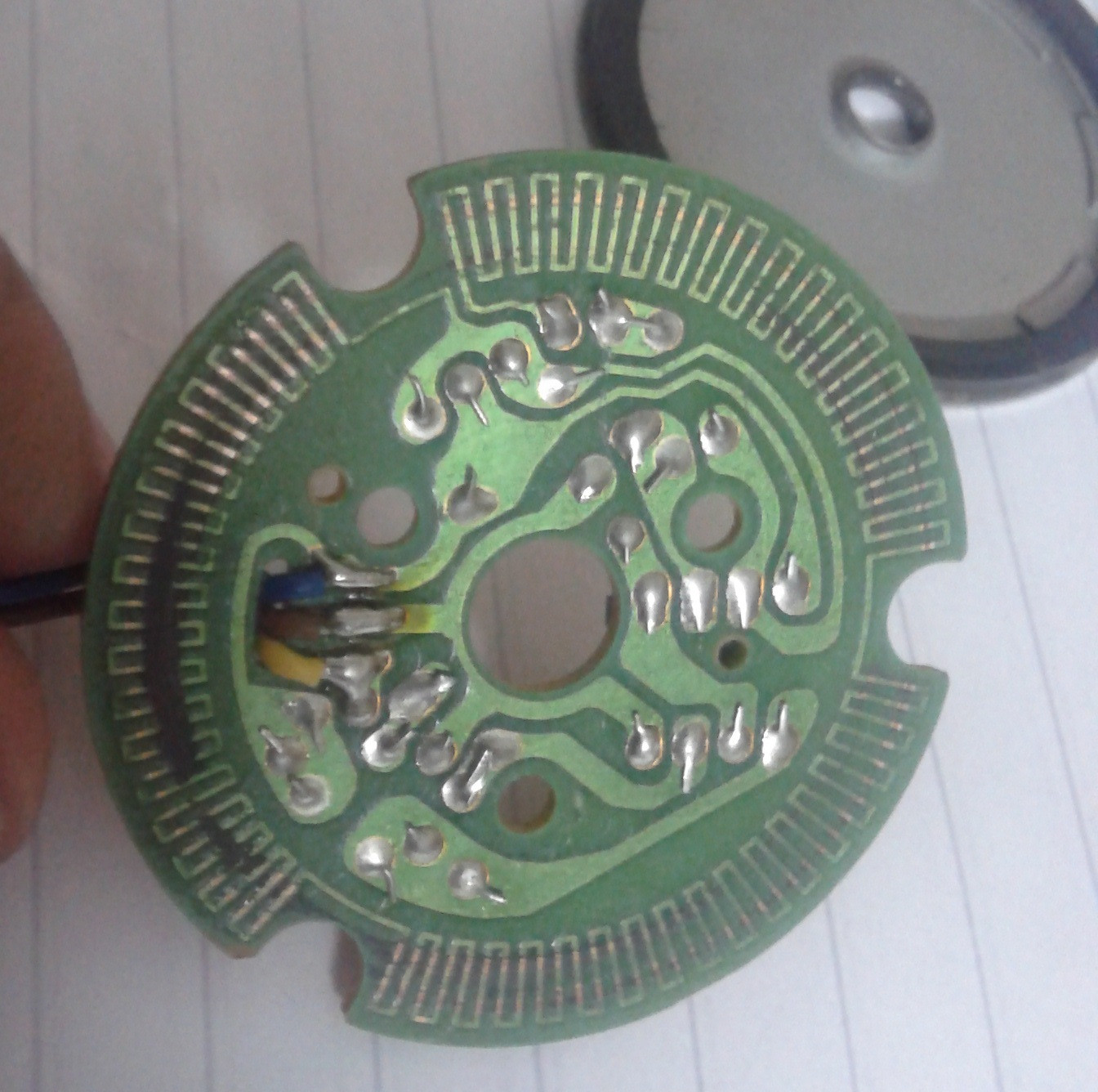
I have found this circuit mounted to a DC motor. It is probably an encoder but I don't know how it works. I have looked everywhere but I could not find a similar encoder assuming that this is in fact one. The circuit is placed on a motor casing in a way that does not allow it to rotate or move. The PCB part with green solder mask is facing away from the motor. A metallic disk with a magnetic ring on top of it is attached to the motor shaft facing the green mask and is allowed to rotate freely with the shaft. The electronic components on the PCB are caps, resistors, dual operational amplifier (IC BA728) and a regular NPN transistor (C3311). Can someone identify the type of this encoder? or better yet explain how it operates?

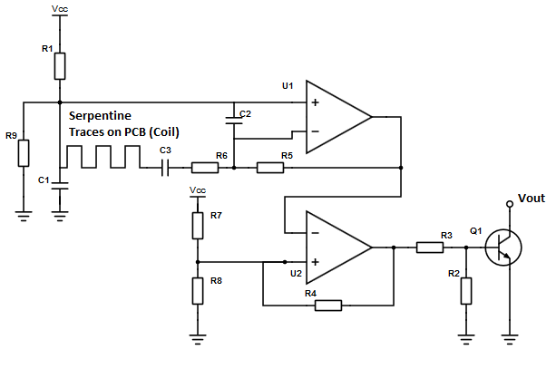
(I Modified the schematic again. Thanks, curd.)

\$\endgroup\$
8
  • \$\begingroup\$ It would help to see the rotating part of the motor w/shaft. If there are rotating magnets then this would be a direct drive motor. It is not a rotary encoder (there would need to be contacts on the PCB). \$\endgroup\$
    – user3169
    Commented Jul 21, 2015 at 5:05
  • \$\begingroup\$ Drawing the circuit diagram would help. The PCB is quite simple, it has not too many parts and is one sided so it's easy to do. \$\endgroup\$
    – Curd
    Commented Jul 21, 2015 at 7:38
  • \$\begingroup\$ Please use images cropped down to the necessary, that makes them appear bigger within the post without having to open them externally. As others have mentioned without a schematic it is even more guess work, so help us to help you and quickly draw one. \$\endgroup\$
    – PlasmaHH
    Commented Jul 21, 2015 at 9:27
  • 1
    \$\begingroup\$ I believe its a Tachometer, not an encoder \$\endgroup\$ Commented Jul 21, 2015 at 20:09
  • 1
    \$\begingroup\$ There is a mistake in the schematic at the + input (pin 5) of the the second OpAmp (U2). One of the three resistors at the + input is going to GND, one is going to Vcc and one (R4) is going to the output. It works as comparator with hysteresis (i.e. Schmitt-trigger; pos. feedback is via R4). \$\endgroup\$
    – Curd
    Commented Jul 22, 2015 at 13:51

2 Answers 2

4
\$\begingroup\$

You'll notice that there are 8 magnets, but the "coil" (the serpentine traces) have 3-fold symmetry. This means that as the magnets rotate, the induced voltage in the pickup will vary with rotation, with a period 3 x 8 or 24 (EDIT - oops, 12, since the magnets need to alternate north and south) times the shaft rotation rate. This varying voltage is AC-coupled to the first op amp, where it is amplified and passed to the second. The second adds more gain and effectively half-wave rectifies the signal since the op amp is running single-ended. The output of the second op amp drives the base of the output transistor, so you get 24 (EDIT - 12) open-collector pulses per revolution.

Depending on the gains involved and the strength of the magnets, this will only provide reliable operation over a particular range of shaft velocities, so it is technically a shaft encoder, but unlike optical encoders it can only be used for velocity, not position, control.

It is probably used to provide precision locking of the motor to a reference speed, which cannot be done with "standard" tachometers due to voltage coefficient uncertainties and line loss, or to provide a precision rotation signal and is possibly intended for an application like use of a chopper wheel with a lock-in amplifier.

\$\endgroup\$
9
  • 1
    \$\begingroup\$ @luchador - Sigh. No. The magnets alternate north/south around the rim, so you DO have AC. And yes, the inputs on both op amps are switched, but I already said that. \$\endgroup\$ Commented Jul 22, 2015 at 13:34
  • 1
    \$\begingroup\$ @luchador - That would be true if it were not for the 3 interruptions in the pattern. They are important. \$\endgroup\$ Commented Jul 22, 2015 at 13:41
  • 1
    \$\begingroup\$ I haven't noticed the 8 alternating magnets. Now it makes sense! \$\endgroup\$
    – Curd
    Commented Jul 22, 2015 at 14:10
  • 1
    \$\begingroup\$ BTW: the 2nd OpAmp works as Schmitt-trigger. The schematic is wrong about the three resistors at the positive input. Actually two of the form a voltage divider between Vcc and GND. One of them comes back from the output to give positive feedback for hysteresis. \$\endgroup\$
    – Curd
    Commented Jul 22, 2015 at 14:15
  • 1
    \$\begingroup\$ @Curd - Ooh. Good catch. I'd wondered about the two resistors in parallel. And it does increase the dynamic range wrt shaft speed by making the pulse transitions more stable than they would be if the op amp were just using asymmetric swings. \$\endgroup\$ Commented Jul 22, 2015 at 14:48
1
\$\begingroup\$

The zig-zag is designed to intersect the magnetic field of that magnet. It must have not been constructed as a series of opposite poles horizontally, it must be of same poles vertically. In that way it will expose the magnetic field which the zigzag can intersect most perpendicularly. The change of the rotation angle will induce a potential on the zigzag. So, the output of the circuit is proportional to the angular speed. Sorry for my bad language.

\$\endgroup\$

Your Answer

By clicking “Post Your Answer”, you agree to our terms of service and acknowledge you have read our privacy policy.

Not the answer you're looking for? Browse other questions tagged or ask your own question.